

Fixture for supporting a workpiece
- Summary
- Abstract
- Description
- Claims
- Application Information
AI Technical Summary
Benefits of technology
Problems solved by technology
Method used
Image

Examples
Embodiment Construction
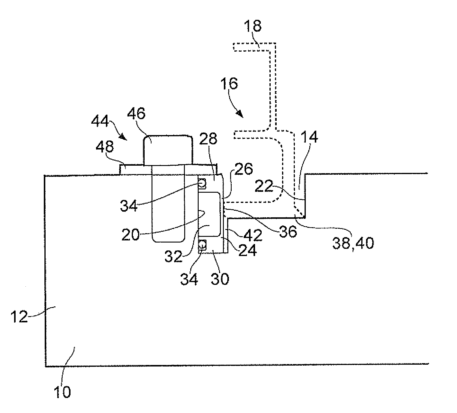
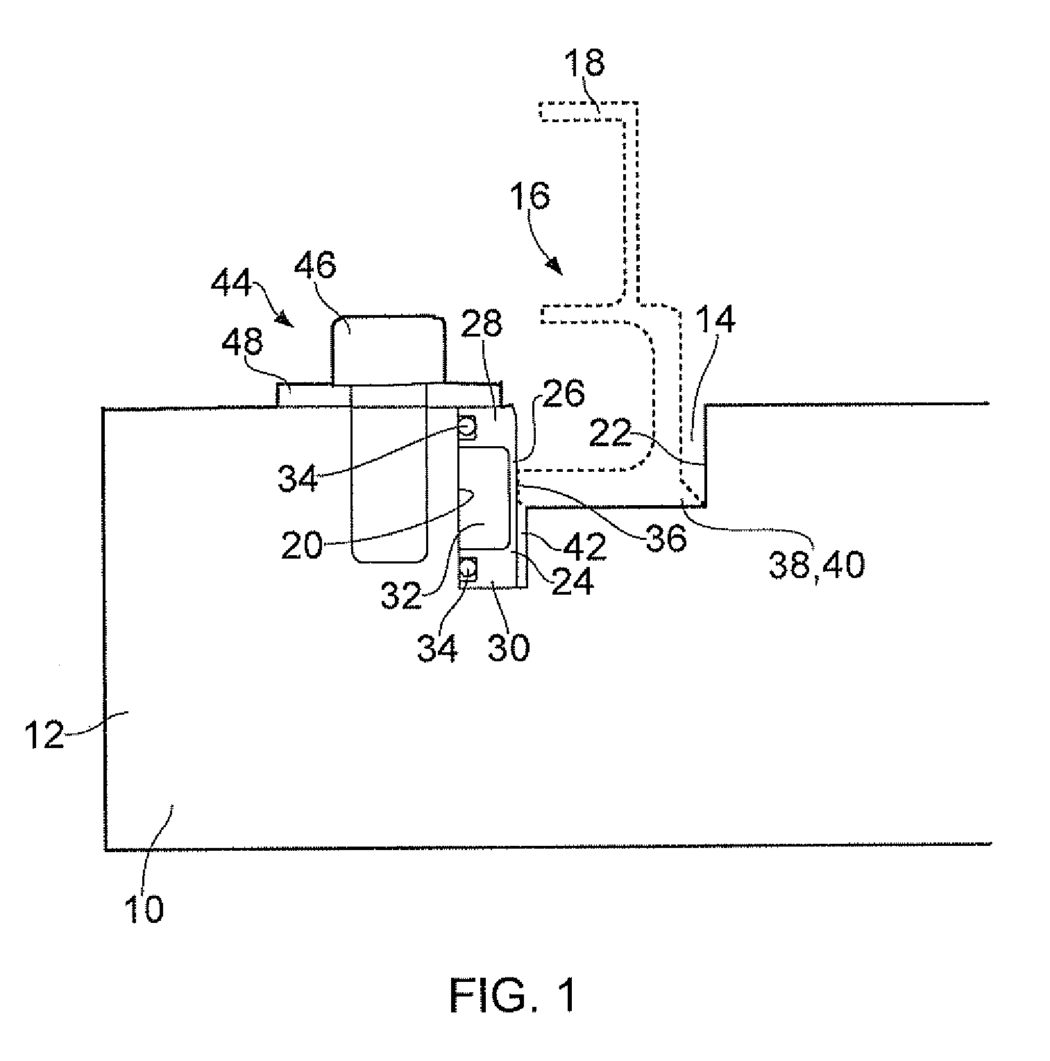
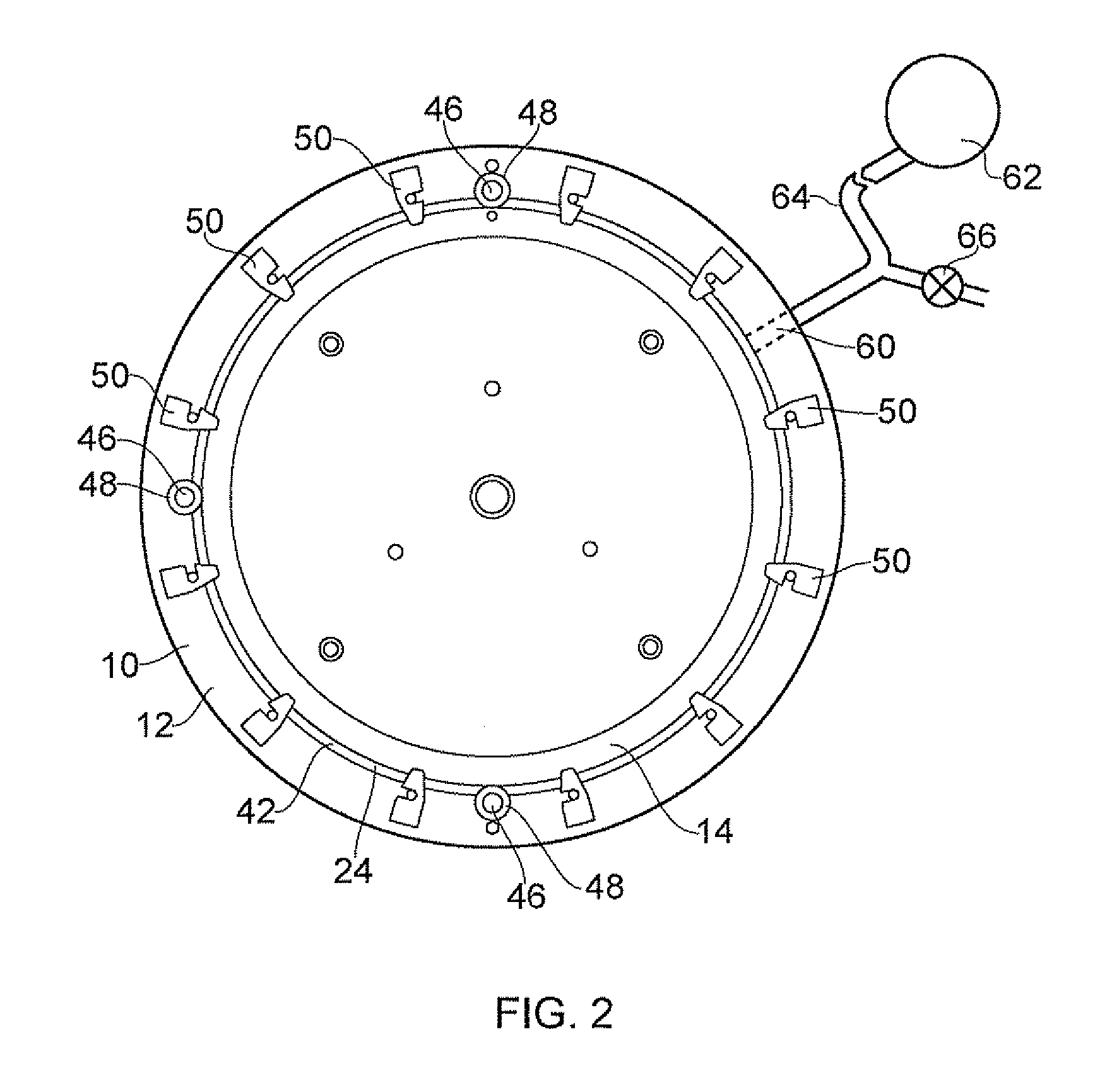
[0015]Shown in FIG. 1 is a fixture 10 according to the present invention. The fixture 10 comprises a base 12 provided with a channel 14 for receiving part, or region, 16 of a workpiece 18 (shown in a dotted line). The channel 14 has a first wall 20 facing an opposing second wall 22. An inflatable diaphragm 24 is located on the first wall 20. As shown in the plan view of FIGS. 2 and 3, the channel 14 is substantially annular. FIG. 2 shows the fixture 10, and FIG. 3 shows the fixture 12 with the workpiece 18 installed. For added clarity, a perspective view is shown in FIG. 4.
[0016]The diaphragm 24 comprises a deformable portion 26 spaced apart from the first wall 20 of the channel 14. The deformable portion 26 has ends 28,30 which provide a seal with the first wall 20 to define a chamber 32 enclosed by the first wall 20 and diaphragm 24. The ends of the diaphragm 24 are substantially thicker than the deformable portion 26. A sealing member 34 is provided between at least one of the en...
PUM
| Property | Measurement | Unit |
|---|---|---|
| Elasticity | aaaaa | aaaaa |
Abstract
Description
Claims
Application Information