Seat Frame For A Folding Chair

Inactive Publication Date: 2011-04-14
LIN MEI CHUEN +1
View PDF4 Cites 4 Cited by
  • Summary
  • Abstract
  • Description
  • Claims
  • Application Information

AI Technical Summary

Benefits of technology

[0007]A primary objective of the present invention is to provide a structure in which the seat cushion is directly fixed on the seat frame so as to overcome the foregoing disadvantages regarding the assembly between the seat cushion and the seat frame, and increase the bearing load of the seat cushion.
[0008]To achieve the objective mentioned above, a seat frame for a folding chair according to the present invention includes a support rail of an increased size that extends from a bottom edge of the seat frame toward a central area of the seat frame, the support rail being used for placing a seat cushion. A plurality of through-holes is formed on the support rail, and a plurality of threaded holes is formed through a bottom of the seat cushion corresponding to the through-holes. A plurality of fasteners is engaged via the through-holes with the threaded holes so as to fix the seat cushion on the seat frame.
[0009]The support rail has an increased width allowing engagement of the fasteners for directly fixing the seat cushion on the support rail of the seat frame. As a result, the seat frame has enhanced strength for sustaining a load thereon.

Problems solved by technology

However, the seat cushion A is not directly fixed on the seat frame C. Instead, the seat cushion A is placed on the support rail C1 and fixed with the brackets D. In turn, the brackets D are only fixed with the seat cushion and do not have any locking connection with the seat frame, which only acts to clamp the brackets D. As a result, after the seat cushion is used for a long period of time, the brackets D may deform, rust or loosen, which may deteriorate its fixing with the seat cushion.
The seat frame of the conventional folding chair therefore cannot provide strong support for sustaining heavier load.

Method used


Image

  • Seat Frame For A Folding Chair
  • Seat Frame For A Folding Chair
  • Seat Frame For A Folding Chair

Examples


Embodiment Construction

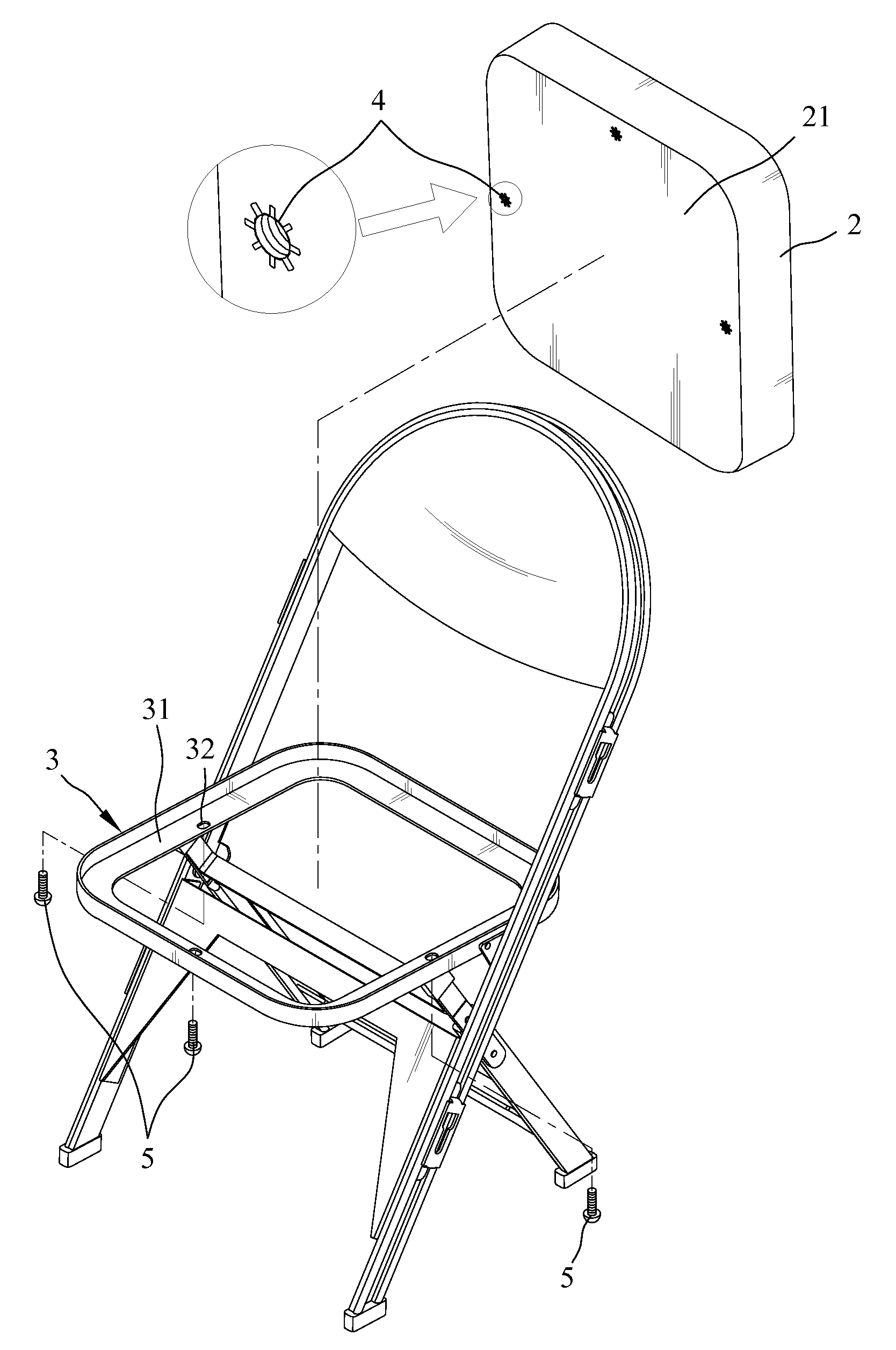
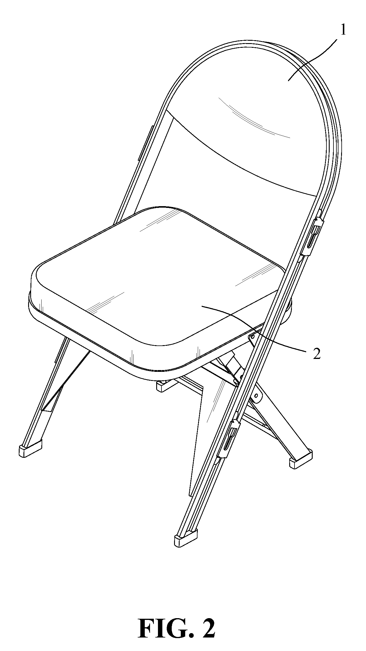
[0015]Referring to FIGS. 2 and 3, a seat cushion 2 of a folding chair include a wooden base 21 formed from plywood or other wood material, a plurality of layers of foam or like soft material disposed on the wooden base 21 and leather encapsulating the wooden base 21 and the foam or like soft material. Studs securely fixed the wooden base 21 with the leather. A backrest cushion 1 of the folding chair has a structure similar to that of the seat cushion 2.

[0016]FIGS. 2, 3 and 4 are explosive views showing a folding chair having a seat frame 3 according to an embodiment of the present invention. The seat frame 3 has a size corresponding to the seat cushion 2. A bottom edge of the seat frame 3 includes a support rail 31 of an increased size that extends toward a central area of the seat frame 3. More particularly, the support rail 31 has an extended width h2 of about 1.8 cm for improved support. However, the extended width h2 is not limited to 1.8 cm (the support rail of a conventional f...


PUM


Abstract

A seat frame for a folding chair includes a support rail of an increased size that extends from a bottom edge of the seat frame toward a central area of the seat frame. The support rail is used for placing a seat cushion of the folding chair thereon. A plurality of through-holes is formed on the support rail, and a plurality of threaded holes is formed through a bottom of the seat cushion corresponding to the through-holes. When the seat cushion is placed on the support rail, the threaded holes are in alignment with the through-holes, and a plurality of fasteners are engaged via the through-holes with the threaded holes so as to directly fix the seat cushion on the support rail of the seat frame. The strength of the seat cushion for sustaining a load can be thereby enhanced.

Description

BACKGROUND OF THE INVENTION[0001]1. Field of the Invention[0002]The present invention generally relates to a seat frame for a folding chair, and more particularly to a folding chair having a backrest and a seat cushion including a foam material, the seat cushion being directly fixed on a seat frame.[0003]2. The Prior Arts[0004]FIG. 1 is an exploded view showing a conventional folding chair. A seat cushion A of the folding chair includes a cushion portion and a wooden base A1. The cushion portion has multiple layers of foam or like soft materials enveloped by a layer of leather. A plurality of internally threaded rivets B is then used to fix the cushion portion onto the wooden base A1, thereby forming the seat cushion A.[0005]The metal seat frame C has a support rail C1 at the periphery thereof Usually, a width h1 of the support rail C1 is only about 1 cm. When the seat cushion A is assembled with the seat frame C, fasteners having larger diameters can not be used as fixture. As a re...

Claims


Application Information

Patent Timeline
IPC IPC(8): A47C7/02A47C4/00
CPCA47C7/185A47C4/24
Inventor LIN, MEI CHUENWANG, TZU MEI
Owner LIN MEI CHUEN
Why Eureka
Try Eureka