Inductively powered electric component of an MRI apparatus

a technology of inductive power and electric components, which is applied in the direction of reradiation, measurement using nmr, instruments, etc., can solve the problems of affecting the patient, deteriorating image quality, and unwanted displacement of modules, so as to reduce the number of magnetic field lines, reduce the induced current, and achieve maximum electric power.

Active Publication Date: 2011-04-14
KONINKLIJKE PHILIPS ELECTRONICS NV
View PDF11 Cites 25 Cited by
  • Summary
  • Abstract
  • Description
  • Claims
  • Application Information

AI Technical Summary

Benefits of technology

[0012]This has the advantage that in the frequency band, which is used for acquisition of magnetic resonance imaging signals, no disturbances due to the inductively supplied electric power occur. This allows avoiding excessive filtering of the higher harmonics of the power transfer frequency. Hence, disturbances due to improper selection of the operating frequency of the inductive power transfer system are avoided.
[0031]The special arrangement of coils provides the further advantage, that the electric component, especially a receiver coil unit can be inductively powered over the complete cross-section of the MRI tube. This is an important aspect since depending on the imaged object position, size of the imaged object etc., the receiver coil unit will be located within the MRI tube at almost any arbitrary spatial position. By combining the features of the rotating magnetic fields, was well as the set of transmitter coils, wherein the windings of each transmitter coil of the set of transmitter coils span a plane, wherein all spanned planes of the set of transmitter coils intersect with a common axis, wherein said axis is parallel with the cylindrical axis of the main magnet, an operator of the MRI system is completely free to position the receiver coil unit at any arbitrary position and orientation on an imaged object within the MR bore.

Problems solved by technology

However, the usage of cables to connect the coil modules to the MRI system has various disadvantages.
For example, the comparably stiff cables may be the cause for an unwanted displacement of the modules during movement of the patient.
Furthermore, in some cases common mode currents may be induced in the cables which deteriorate the image quality and even may cause harm to the patient.
However, there may arise the problem that unwanted disturbances of the sensor coils may occur since the sensor coils are extremely sensitive against any disturbances in the RF (radio frequency) range around the MR frequency.

Method used


Image

  • Inductively powered electric component of an MRI apparatus
  • Inductively powered electric component of an MRI apparatus
  • Inductively powered electric component of an MRI apparatus

Examples


Embodiment Construction

[0043]In the following similar elements are depicted by the same reference numerals.

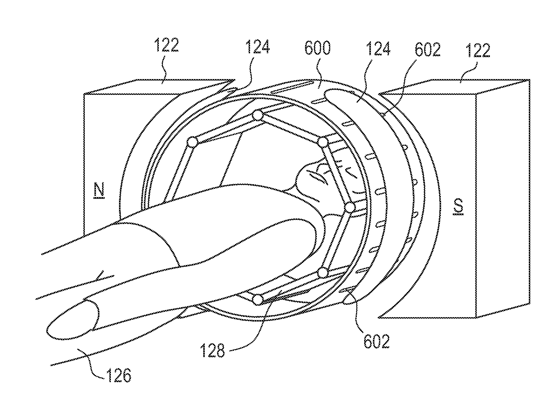
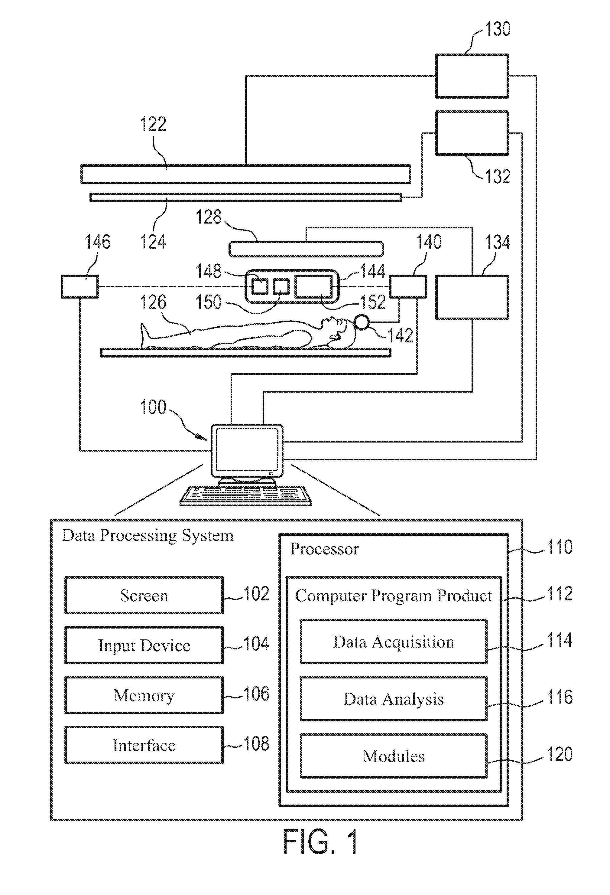
[0044]FIG. 1 is a schematic illustrating an MRI system according to the invention. Only major components of a preferred MRI system which incorporate the present invention are shown in FIG. 1. The magnetic resonance imaging apparatus comprises a data processing system 100, wherein the data processing system 100 typically comprises a computer screen 102 and an input device 104. Such an input device could be for example a keyboard or a mouse. The MRI system further comprises a memory 106 and an interface 108. The interface 108 is adapted for communication and data exchange with typical hardware MRI components.

[0045]Typical hardware MRI components are for example a main field control unit 130 adapted for controlling the main field of the magnet 122. The interface 108 is also adapted to communicate with the gradient coil unit 132, wherein respective gradient coils 124 are preferably self shielded gradient...


PUM


Abstract

The invention relates to a nuclear magnetic resonance imaging apparatus comprising: a main magnet (122) adapted for generating a main magnetic field; at least one radio frequency receiver coil unit (144) for acquiring magnetic resonance signals in a receiver coil radio frequency band (202) from an examined object (124); means (140) for inductively (wirelessly) supplying electric power to an electric component of the apparatus, wherein the electric component is adapted to be powered by inductively supplied electric power, wherein the power transfer frequency (200) and the higher-harmonics (206) of the power transfer frequency (200) for inductively supplying the electric power are located outside the receiver coil radio frequency band (202).

Description

TECHNICAL FIELD[0001]The invention relates to a nuclear magnetic resonance imaging apparatus, a nuclear magnetic resonance imaging receiving coil, a method of performing nuclear magnetic resonance imaging of an object, a method of acquiring magnetic resonance image signals and a computer program product.BACKGROUND AND RELATED ART[0002]Magnetic resonance imaging (MRI) is a state of the art imaging technology which allows cross sectional viewing of objects like the human body with unprecedented tissue contrast. MRI is based on the principles of nuclear magnetic resonance (NMR), a spectroscopic technique used by scientists to obtain microscopic chemical and physical information about molecules. The basis of both NMR and MRI is the fact, that atomic nuclei with non-zero spin have a magnetic moment. In medical imaging, usually nuclei of hydrogen atoms are studied since they are present in the body in high concentrations like for example water. The nuclear spin of elementary particles can...

Claims


Application Information

Patent Timeline
Patent Type & Authority Applications(United States)
IPC IPC(8): G01R33/44
CPCG01R33/283G01R33/422G01R33/3692G01R33/3642
Inventor WAFFENSCHMIDT, EBERHARDHILGERS, ACHIMDE VRIES, LAMBERTUSWEISSLER, BJOERNREEFMAN, DERKVAN HELVOORT, MARINUS JOHANNES ADRIANUS MARIABLANDEN, PIETER GERRIT
Owner KONINKLIJKE PHILIPS ELECTRONICS NV
Why Eureka
Try Eureka