
Total bandwidth conditioning device

a technology of signal conditioning and bandwidth, applied in the direction of digital transmission, electrical cable transmission adaptation, electrical apparatus, etc., can solve the problems of channel loss, channel exceeding the level specification, and devices that require expensive testing equipment to determine whether, so as to reduce the effect of undesirable interference signals

Inactive Publication Date: 2011-04-14
PPC BROADBAND INC
View PDF99 Cites 37 Cited by
  • Summary
  • Abstract
  • Description
  • Claims
  • Application Information

AI Technical Summary

Benefits of technology

[0015]The present invention helps to reduce the effect of undesirable interference signals that are unknowingly injected into the main signal distribution system, through the upstream bandwidth, by a user.
[0016]In accordance with one embodiment of the present invention, a device is provided for conditioning a total bandwidth. The device includes a return path extending at least a portion of a distance between a supplier side connector and a user side connector, and a forward path extending at least a portion of a distance between the supplier side connector and the user side connector. An upstream section including a variable signal level adjustment device connected within the return path. A downstream section including a forward coupler connected within the forward path. The device further includes at least one microprocessor. The microprocessor is connected electrically upstream the variable signal level adjustment device. The microprocessor reduces an amount of signal level adjustment applied to the return path in response to a reduction in a level of a downstream bandwidth at the forward coupler.

Problems solved by technology

While all channels experience some loss, channels transmitted using higher frequencies within the downstream bandwidth experience more loss than those transmitted using lower frequencies.
In turn, if there is a large amount of slope present, such as when a user's premise includes long distances of signal cable, the drop-style amplifier may cause some channels to exceed their level specification while other channels may remain below their specification.
However, these devices require expensive testing equipment to determine whether and / or how much slope compensation should be supplied to a particular premise.
Further, due to the cost of installation and a general misunderstanding regarding how to install such devices, there are relatively few in existence, compared to the number of such devices needed.
Many generators of such undesirable interference signals are electrical devices that inadvertently generate electrical signals as a result of their operation.
While the RF signals generated by these latter devices are desirable for their intended purposes, these signals will conflict with the desirable upstream information signals if they are allowed to enter the CATV system.
Undesirable interference signals, whether they are inadvertently generated electrical signals or intentionally created RF signals, may be allowed to enter the CATV system, typically through an unterminated port, an improperly functioning device, a damaged coaxial cable, and / or a damaged splitter.
However, when there is no coaxial cable or no device connected to a port the center conductor is exposed to any undesirable interference signals and will function like a small antenna to gather those undesirable interference signals.
Similarly, a coaxial cable or device having damaged or malfunctioning shielding may also gather undesirable interference signals.
This issue is further compounded by the number of users connected together within a particular distribution network, especially knowing that one user can easily impact all of the other users.
Attempts at improving an overall signal quality of the upstream bandwidth have not been successful using traditional methods.
The inherent presence of the undesirable interference signals in the upstream bandwidth generated by each user has typically precluded the use of these typical, drop amplifiers to amplify the upstream bandwidth, because the undesirable interference signals are amplified by the same amount as the desirable information signals.
Accordingly, the signal-to-noise ratio remains nearly constant, or worse, such that the overall signal quality of the upstream bandwidth is not increased when such a typical, drop amplifier is implemented.

Method used


Image

  • Total bandwidth conditioning device
  • Total bandwidth conditioning device
  • Total bandwidth conditioning device

Examples


Embodiment Construction

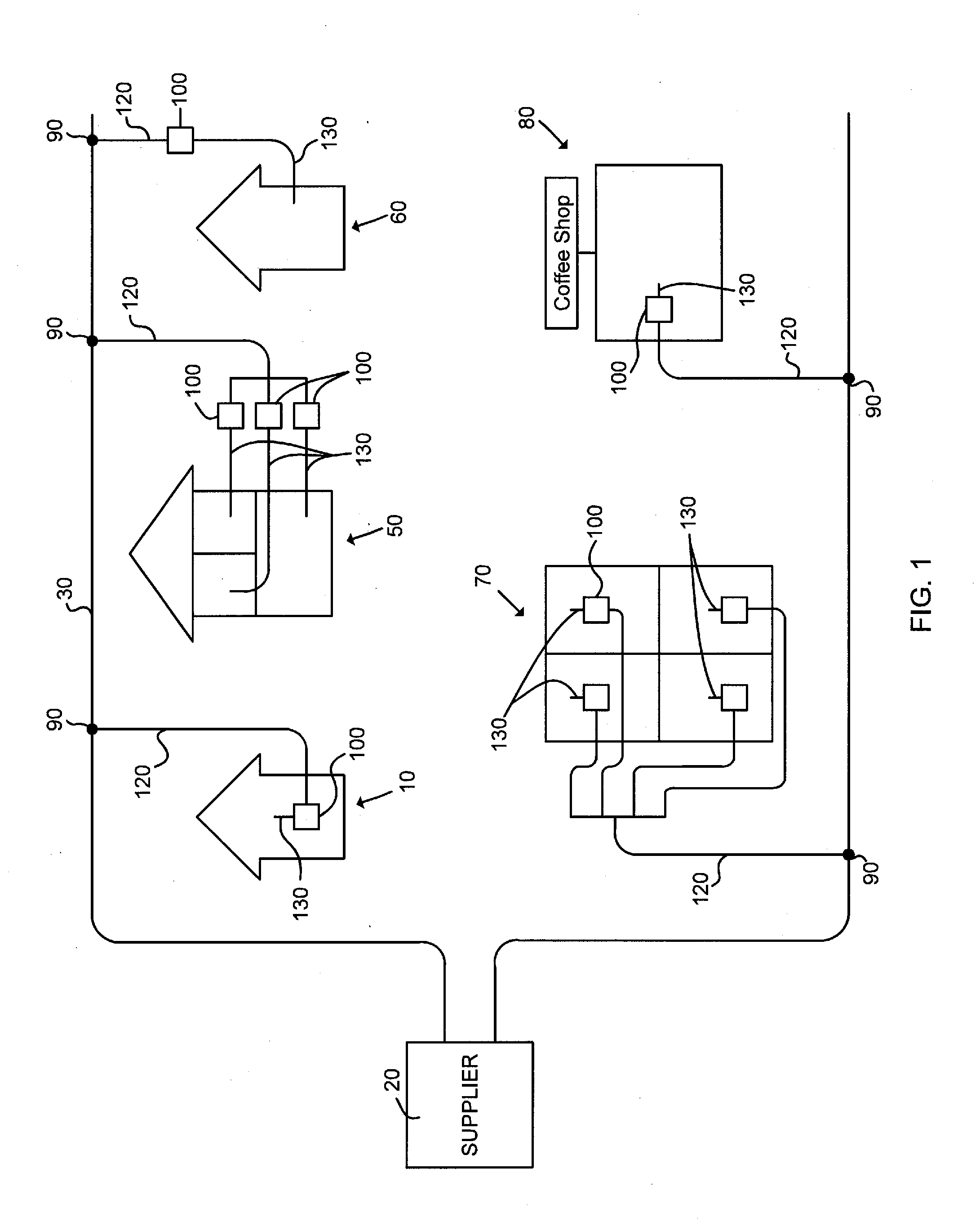
[0041]As shown in FIG. 1, a CATV system typically includes a supplier 20 that transmits a downstream bandwidth, such as RF signals, digital signals, and / or optical signals, to a user through a main distribution system 30 and receives an upstream bandwidth, such as RF signals, digital signals, and / or optical signals, from a user through the same main signal distribution system 30. A tap 90 is located at the main signal distribution system 30 to allow for the passage of the downstream / upstream bandwidth from / to the main signal distribution system 30. A drop transmission line 120 is then used to connect the tap 90 to a house 10, 60 an apartment building 50, 70, a coffee shop 80, and so on. As shown in FIG. 1, a total bandwidth conditioning device 100 (“conditioning device 100”) of the present invention may be connected in series between the drop transmission line 120 and a user's premise distribution system 130.

[0042]Referring still to FIG. 1, it should be understood that the condition...


PUM


Abstract

A device for conditioning a total bandwidth includes a return path extending at least a portion of a distance between a supplier side connector and a user side connector, and a forward path extending at least a portion of a distance between the supplier side connector and the user side connector. An upstream section including a variable signal level adjustment device connected within the return path. A downstream section including a forward coupler connected within the forward path. The device further includes at least one microprocessor. The microprocessor is connected electrically upstream the variable signal level adjustment device. The microprocessor reduces an amount of signal level adjustment applied to the return path in response to a reduction in a level of a downstream bandwidth at the forward coupler.

Description

FIELD OF THE INVENTION[0001]The present invention relates generally to signal conditioning devices for use in community antenna television (“CATV”) systems, and in particular to signal conditioning devices that increases the signal-to-noise ratio of an upstream bandwidth in a CATV system and corrects a level and slope of a downstream bandwidth in the CATV system.BACKGROUND OF THE INVENTION[0002]The use of a CATV system to provide internet, voice over internet protocol (“VOIP”) telephone, television, security, and music services is well known in the art. In providing these services, a downstream bandwidth (i.e., radio frequency (“RF”) signals, digital signals, and / or optical signals) is passed from a supplier of the services to a user, and an upstream bandwidth (i.e., radio frequency (“RF”) signals, digital signals, and / or optical signals) is passed from the user to the supplier. For much of the distance between the supplier and the user, the downstream bandwidth and the upstream ban...

Claims


Application Information

Patent Timeline
Patent Type & Authority Applications(United States)
IPC IPC(8): H04B1/38
CPCH04N7/10H03G3/30
Inventor KELMA, DAVIDCOX, TAB KENDALL
Owner PPC BROADBAND INC
Learn More