Intermediate adapter and camera body
a technology of adapters and camera bodies, applied in the field of intermediate adapters, to achieve the effect of accurate detection
- Summary
- Abstract
- Description
- Claims
- Application Information
AI Technical Summary
Benefits of technology
Problems solved by technology
Method used
Image
Examples
embodiment 1
1. Structure
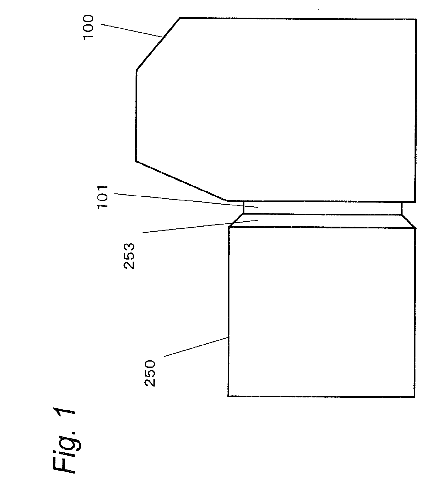
[0023]FIG. 1 is a schematic view showing an imaging system with an interchangeable lens 250 directly attached to a camera body 100. A mount 101 used for attaching the interchangeable lens 250 in a bayonet system is provided on the camera body 100. Here, the interchangeable lens 250 is a lens directly mountable to the camera body 100.
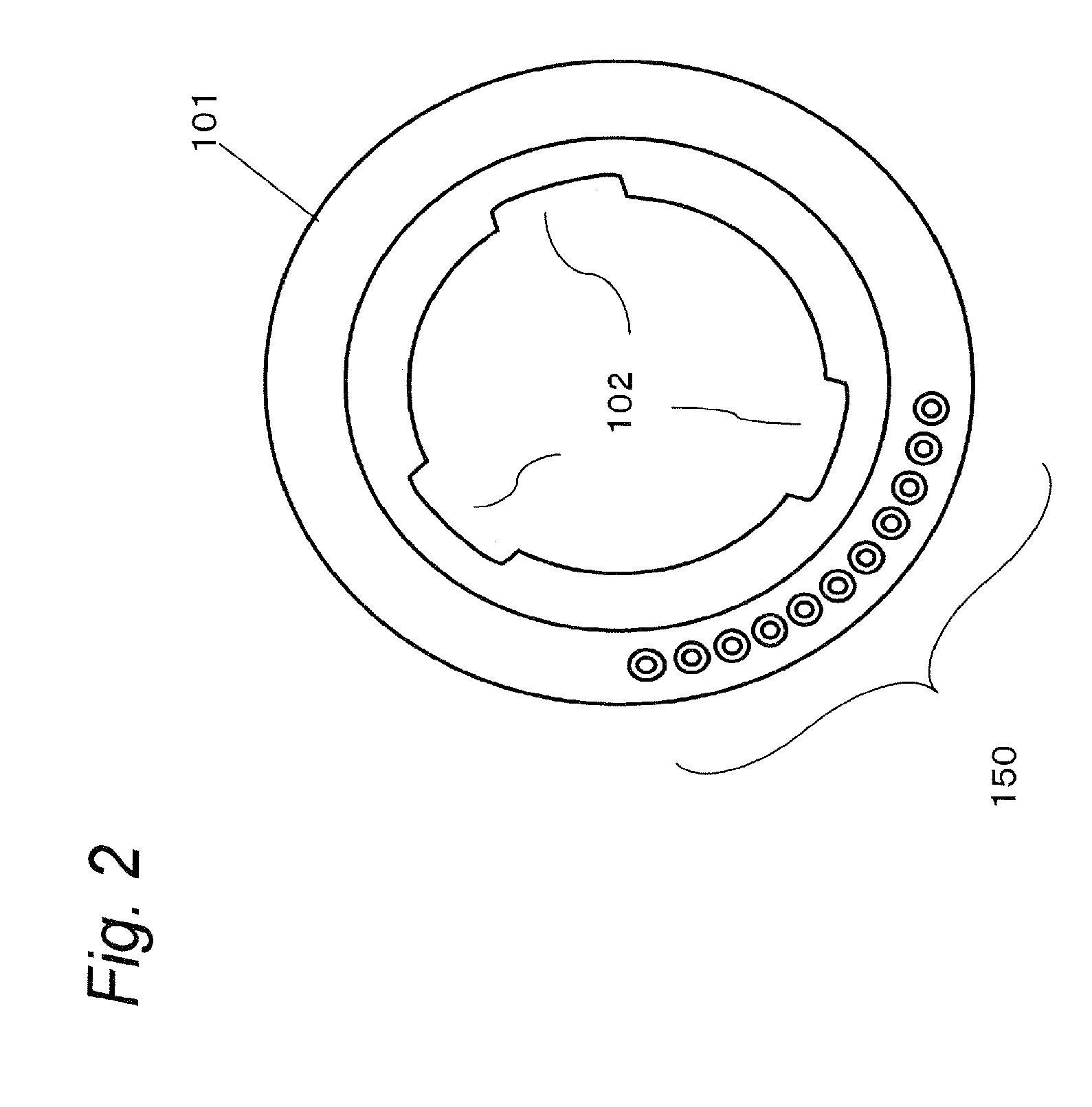
[0024]FIG. 2 is a view showing the mount 101 of the camera body 100 viewed from the front side. The interchangeable lens 250 directly mountable to the camera body 100 can be directly attached to the camera body 100 by inserting a claw (not shown) formed on a joining portion 253 (see FIG. 1) of the interchangeable lens 250 into a cut-out portion 102 of the mount 101 of the camera body 100 and rotating the lens 250 clockwise. Terminals 150 for communicating with the interchangeable lens 250 are provided on the mount 101 of the camera body 100.
[0025]Here, when the shape of the joining portion (203) of the interchangeable lens does not match the ...
embodiment 2
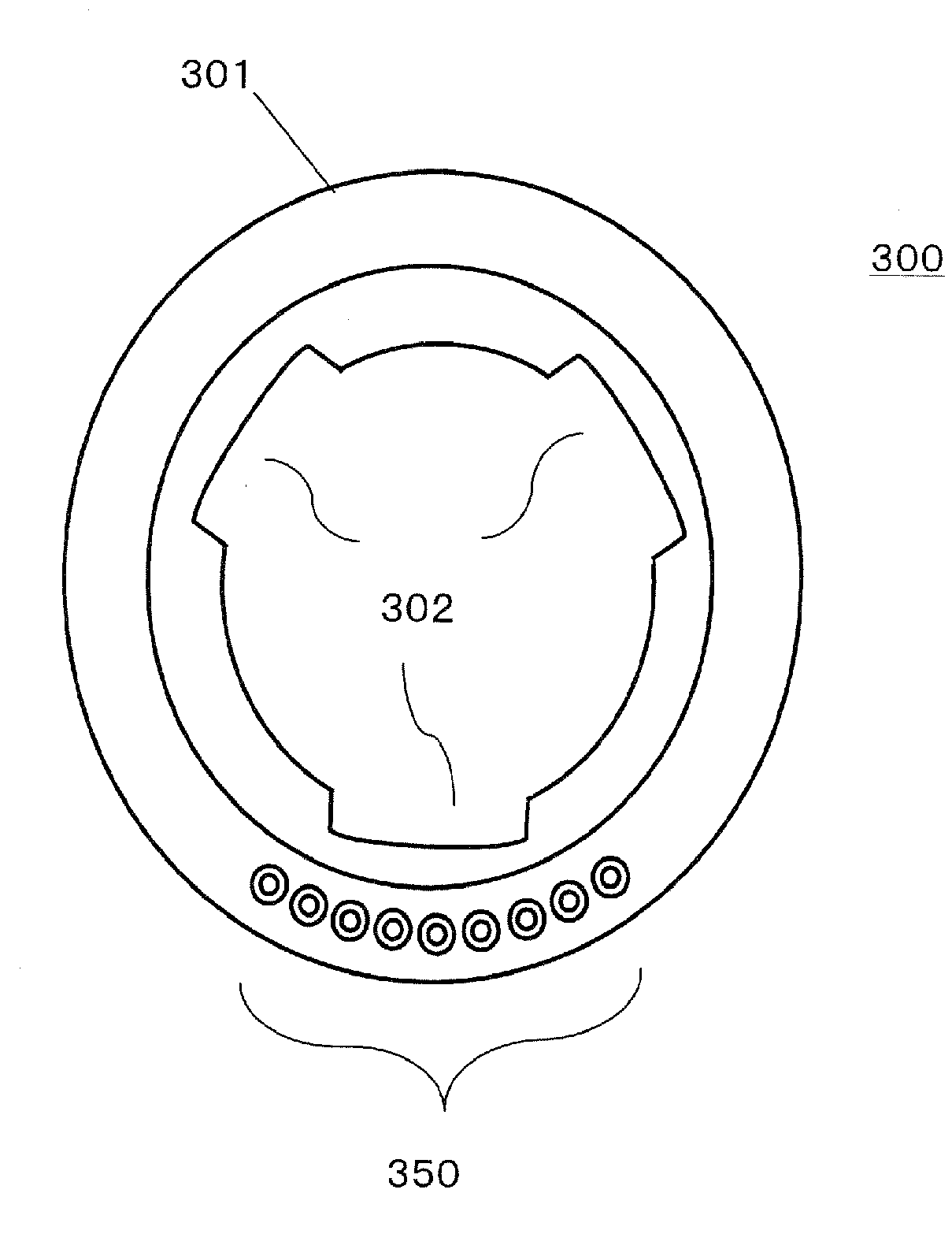
[0048]FIG. 7 shows another example of structure (wiring diagram) of an imaging system. The intermediate adapter 300 and the camera body 100 shown in FIG. 7 differ from those in the structure shown in FIG. 6 of embodiment 1 in structure relating to the switch 106 and the pin 107 for detecting attachment of the adapter. More specifically, in the structure of FIG. 7, the switch 106 and the pin 107 for detecting attachment of the adapter are removed from the camera body 100 in the structure shown in FIG. 6, and in place of these, a switch 308 and a pin 309 for detecting attachment of the adapter are installed in the intermediate adapter 300. Here, a detection unit related to BDET 154 includes a switch 306 and a pin 307 in the same manner as in the structure shown in FIG. 6. Moreover, a terminal (not shown) on the intermediate adapter 300 side for BDET 154 and a terminal (not shown) on the intermediate adapter 300 side for ADET 170 form one example of an informing unit. The other structu...
embodiment 3
[0052]Embodiments 1 and 2 have explained the structure capable of detecting the attachment or not-attachment of the adapter 300 and the interchangeable lens 200 to the camera body 100. The present embodiment will discuss a structure for preventing an erroneous detection during an operation for attaching the intermediate adapter 300 and the interchangeable lens 200.
[0053]The structure of the imaging system of the present embodiment is basically the same as that explained in embodiment 1, however, it differs from embodiment 1 in operations of the switch 106 and the switch 306. Referring to FIG. 8, the following description will discuss the operations of the switch 106 and the pin 107 of the present embodiment.
[0054]FIG. 8A is a view showing status of the switch 106 and the pin 107 when no intermediate adapter 300 is attached to the camera body 100. FIG. 8B is a view showing status of the switch 106 and the pin 107 while the intermediate adapter 300 is being attached to the camera body...
PUM
 Abstract
Description
Claims
Application Information
 - R&D
- Intellectual Property
- Life Sciences
- Materials
- Tech Scout
- Unparalleled Data Quality
- Higher Quality Content
- 60% Fewer Hallucinations
Browse by: Latest US Patents, China's latest patents, Technical Efficacy Thesaurus, Application Domain, Technology Topic, Popular Technical Reports.
© 2025 PatSnap. All rights reserved.Legal|Privacy policy|Modern Slavery Act Transparency Statement|Sitemap|About US| Contact US: help@patsnap.com


