Sealing holes in bony cranial anatomy using custom fabricated inserts

a technology of custom-fabricated inserts and cranial anatomy, which is applied in the field of surgical instruments, can solve the problems of long-term morbidity and the closing of the hole in the skull of the endonasal neurosurgery

Inactive Publication Date: 2011-04-14
LEVATICH MARK
View PDF6 Cites 8 Cited by
  • Summary
  • Abstract
  • Description
  • Claims
  • Application Information

AI Technical Summary

Benefits of technology

[0008]The present invention provides an apparatus and method to implant a seal in a skull base defect with a compound that is initially a viscous fluid and hardens to provide a solid water tight seal to the hole. The seal is implanted using apparatus with deployable elements that are compact so that they may pass up the nasal cavity into the area of the sphenoid sinus where there is room for them to deploy and expand into useful conformations. A disk is inserted through the skull base defect into an interior side of the skull at the skull base defect, with a stalk extending through the skull base defect. The stalk is held outward from the skull base defect, holding the disk against the interior side of the skull while a conical mold is filled with a material that sets to a hardened state. An example of such material is bone cement Once the cement has cured, the apparatus is removed, leaving the insert in the skull with the stalk surrounded by a cone of bone cement, creating a water tight seal in said skull base defect.

Problems solved by technology

However there are cases where the patient has preexisting holes in the bone between the brain cavity and the sinuses.
The most difficult stage of endonasal neurosurgery is closing the hole in the skull.
The patient has a permanent hole in their skull which contributes to long term morbidity.

Method used


Image

  • Sealing holes in bony cranial anatomy using custom fabricated inserts
  • Sealing holes in bony cranial anatomy using custom fabricated inserts
  • Sealing holes in bony cranial anatomy using custom fabricated inserts

Examples


Embodiment Construction

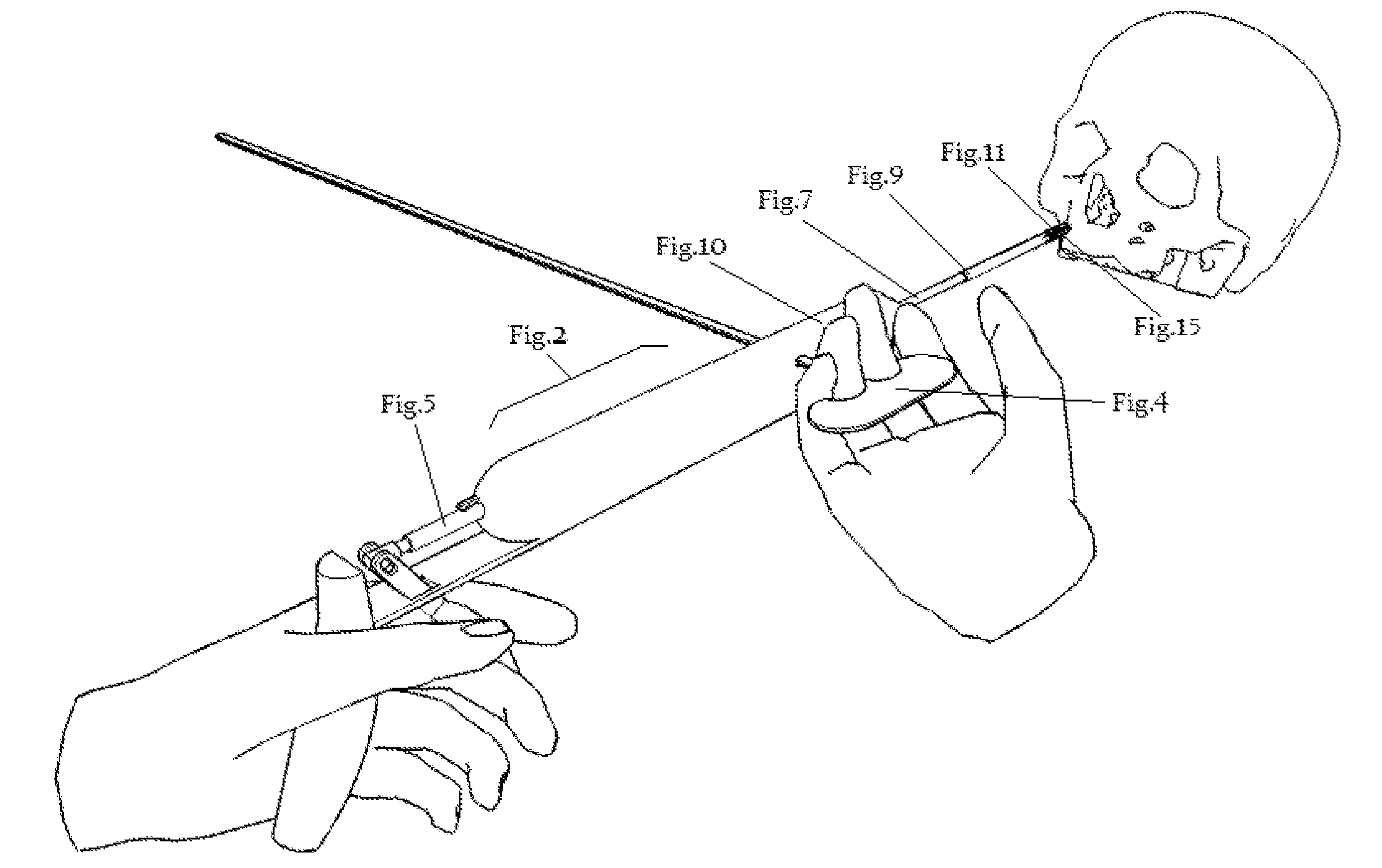
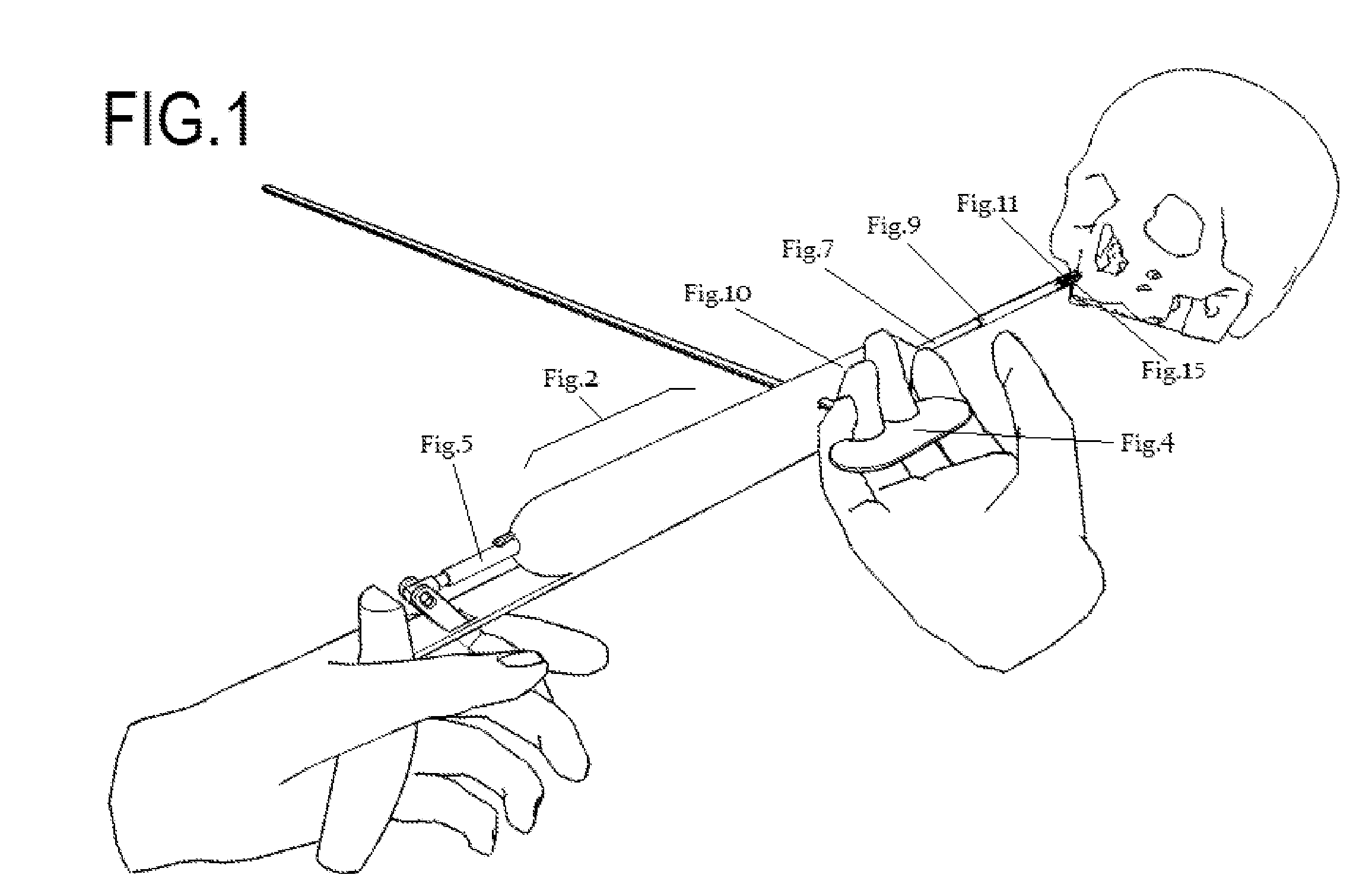
[0045]The invention deploys a prefabricated insert to seal a skull base defect. The first element of the insert is a disk of a flexible material. The disk can be made of harvested tissue, dural graft substitutes, or other flexible biocompatible materials.

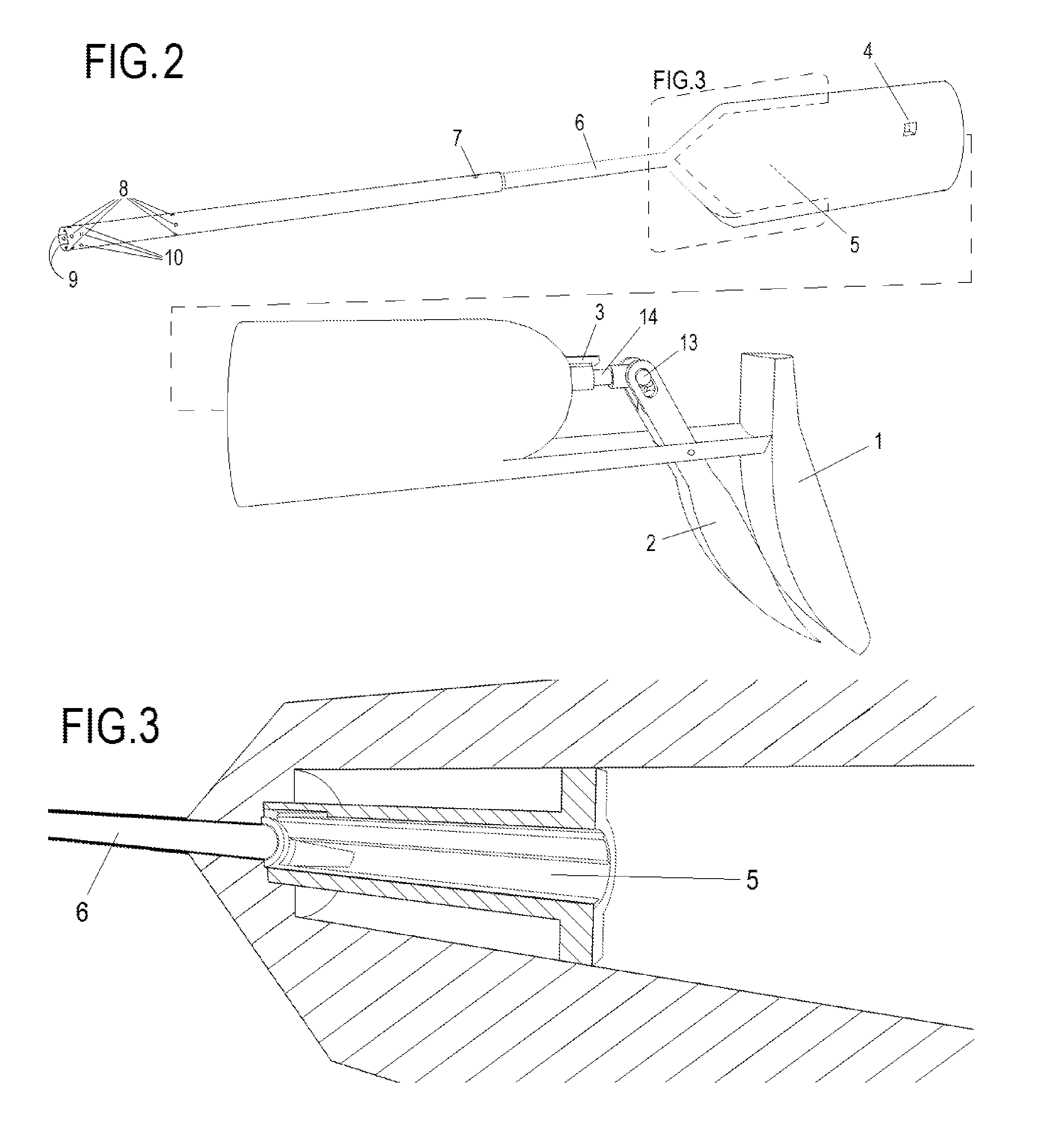
[0046]The flexible material is attached to a central stalk which is pushed by the embodiment to deploy the insert. The central stalk can be made of cured compound so that the stalk will chemically bond to the compound injected or it can be made of another biocompatible compound and held in place when encased in compound to make the seal.

[0047]The insert deploys from being compact within the tip of the embodiment with a series of constraint strings. The strings pass from the flexible disk material to the tip of the embodiment. Pushing of the stalk forward at the center of the graft material and the constraints pulling the edges in the opposite direction forces the graft material to flower open.

[0048]The desired placement of the flexi...


PUM


Abstract

An apparatus and method to implant a seal in a skull base defect. The seal is implanted using apparatus with deployable elements which pass up the nasal cavity into the area of the sphenoid sinus where they deploy and expand into useful conformations. A disk is inserted through the skull base defect into an interior side of the skull at the base defect, with a stalk extending through the skull base defect. The stalk is held outward from the skull base defect, holding the disk against the interior side of the skull while a conical mold is filled with bone cement. Once the cement has cured, the apparatus is removed, leaving the insert in the skull with the stalk surrounded by a cone of bone cement, creating a water tight seal in said skull base defect.

Description

REFERENCE TO RELATED APPLICATIONS[0001]This application claims an invention which was disclosed in Provisional Application No. 61 / 251,036, filed 13 Oct. 2009, entitled “SEALING HOLES IN BONY ANATOMY USING TISSUE REPLACEMENT & BONE CEMENT”. The benefit under 35 USC §119(e) of the United States provisional application is hereby claimed, and the aforementioned application is hereby incorporated herein by reference.FIELD OF THE INVENTION[0002]The invention pertains to the field of surgical instruments. More particularly, the invention pertains to surgical instruments for reconstruction in endonasal neurosurgery.BACKGROUND OF THE INVENTION[0003]One of the existing procedures to remove brain tumors at the skull base is endonasal neurosurgery. This surgery uses the nose and sinuses as a pathway to access the base of the skull. Instruments are used to erode away bone to create a hole in the back of the sinuses through the sphenoid sinus and in proximity to the sella turcica; this area is re...

Claims


Application Information

Patent Timeline
Patent Type & Authority Applications(United States)
IPC IPC(8): A61B17/58A61F2/28
CPCA61B17/842A61B17/8811A61F2/2875A61B17/8861A61B17/8872A61B17/8822
Inventor LEVATICH, MARK
Owner LEVATICH MARK
Why Eureka
Try Eureka