Apparatus and method for solar heat gain reduction in a window assembly

a technology of solar energy and window assemblies, applied in door/window protective devices, building components, constructions, etc., can solve the problems of reducing shg, limiting or blocking sight lines and views, and radiant heat within the space, and achieve the effect of selecting the level of opacity

Inactive Publication Date: 2011-04-21
WESSEL ROBERT B
View PDF51 Cites 73 Cited by
  • Summary
  • Abstract
  • Description
  • Claims
  • Application Information

AI Technical Summary

Benefits of technology

[0006]A window assembly for use in a building is presented. The window assembly has a pane of material. Positioned within the pane are a plurality of spaced-apart micro-louvers which extend substantially across the length of the pane. The micro-louvers are positioned to block transmission of direct sunlight through the pane when the sun is at a selected angle above the horizon or higher. In one embodiment, the micro-louvers are oriented horizontally. The angle at and above which direct light is blocked can be selected to be approximately 30 or 45 degrees above the horizon, for example. The angle can be selected based on the latitude of the location of the window assembly, the time of day during which direct sunlight is blocked, etc. In one embodiment, the micro-louvers are rectangular in cross-section, although other shapes may be used. In one embodiment, the micro-louvers have at least one reflective surface. The micro-louvers may also be partially or completely colored as desired. Additional panes may be used as well. In a preferred embodiment, the micro-louvers are opaque, providing complete blockage of direct sunlight. In alternate embodiments, the micro-louvers are translucent, providing a selected level of opacity.

Problems solved by technology

Problems remain in significantly reducing SHG due to direct sun light.
These solutions have limitations and they limit or block sight lines and views.
Venetian blinds are also an attempt to create shading through obstruction, but they are ineffective in reducing SHG between the window and the blinds, causing radiant heat within the space.

Method used


Image

  • Apparatus and method for solar heat gain reduction in a window assembly
  • Apparatus and method for solar heat gain reduction in a window assembly
  • Apparatus and method for solar heat gain reduction in a window assembly

Examples


Embodiment Construction

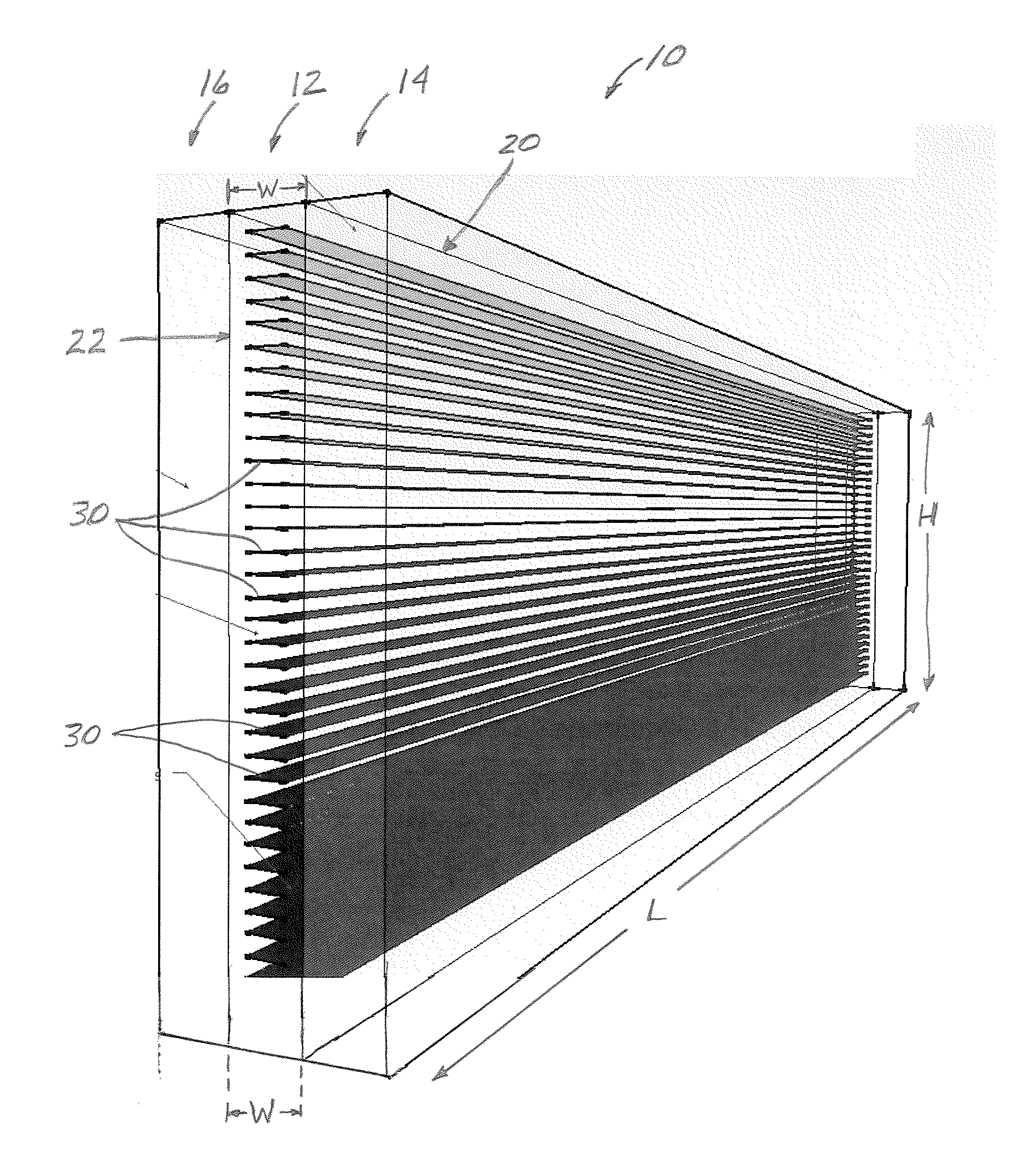
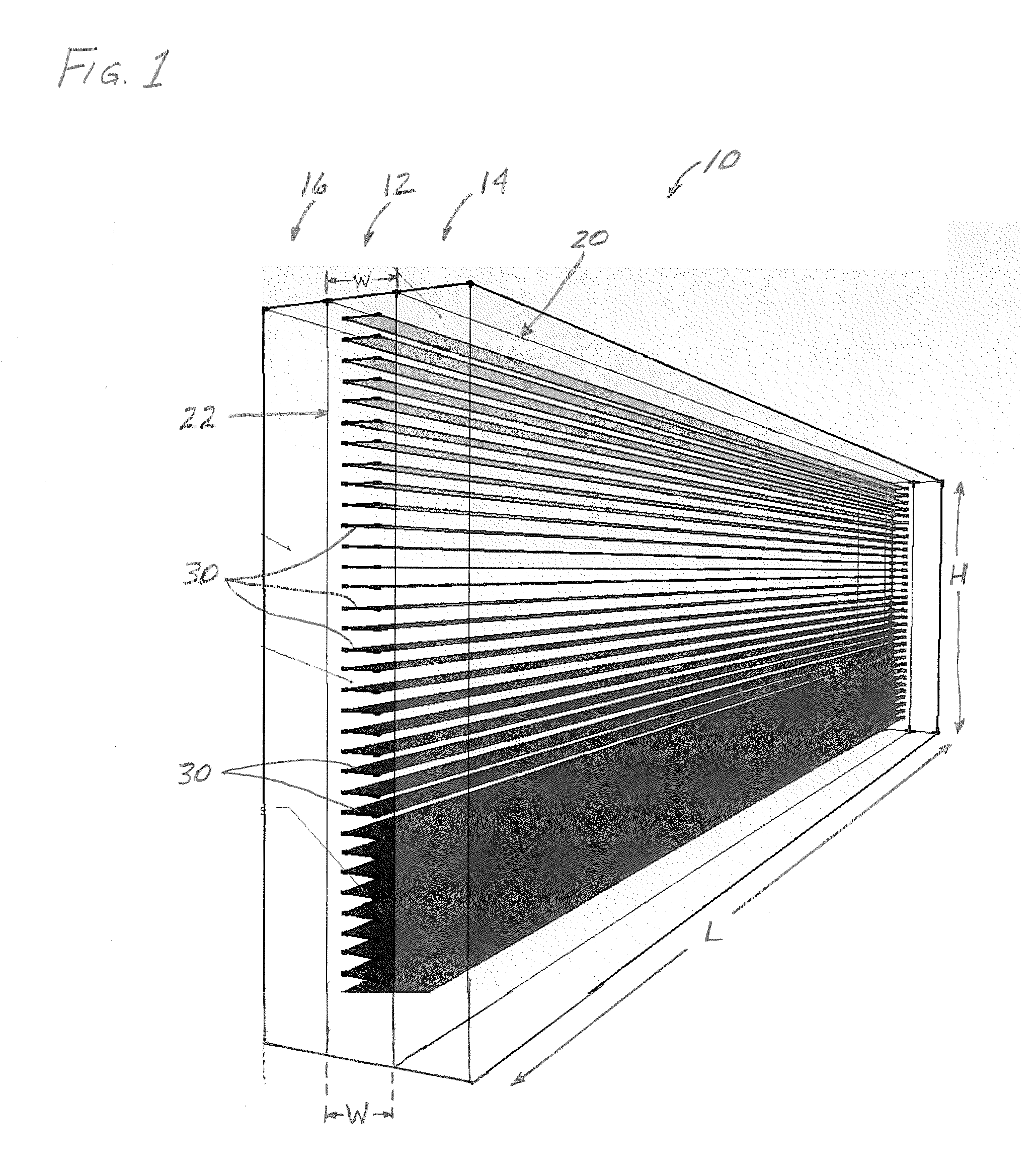
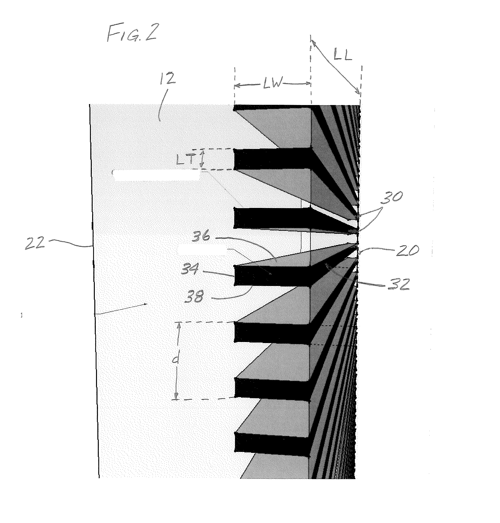
[0014]While the making and using of various embodiments of the present invention are discussed in detail below, a practitioner of the art will appreciate that the present invention provides applicable inventive concepts which can be embodied in a variety of specific contexts. The specific embodiments discussed herein are illustrative of specific ways to make and use the invention and do not delimit the scope of the present invention.

[0015]As used herein, the terms “direct light” or “direct sunlight” refer to direct light in the visible spectrum from the sun. That is, radiation emitted from the sun in the visible spectrum which proceeds in a line to, or is on a line-of-sight with, the object on which it shines. When referring to “direct light” which has been transmitted through a window pane or panes, it is understood that the “direct light” undergoes minor refraction as it passes through the pane or panes. However, the light is still referred to as “direct light” shining on the obje...


PUM


Abstract

A window assembly having at least one pane is presented for use in a building. Positioned within the pane are a plurality of spaced-apart micro-louvers which extend substantially across the length of the pane. The micro-louvers are positioned to block transmission of direct sunlight through the pane when the sun is at a selected angle above the horizon or higher. The angle at and above which direct light is blocked can be selected to be approximately 30 or 45 degrees above the horizon, for example. The angle can be selected based on the latitude of the location of the window assembly, the time of day during which direct sunlight is blocked, etc. The micro-louvers may have reflective surfaces, be colored as desired, be opaque or translucent.

Description

CROSS-REFERENCE TO RELATED APPLICATIONS[0001]This application is a Non-Provisional application claiming priority to the Provisional Application No. 61 / 279,424, filed Oct. 20, 2009, which is incorporated herein by reference for all purposes.FIELD OF INVENTION[0002]The invention relates generally to solar heat gain reduction in window assemblies, and more specifically to an assembly and method to reduce solar heat gain in a window assembly by utilization of micro-louvers positioned in a window pane which block direct sunlight when the sun is at a preselected angle above the horizon and higher.BACKGROUND OF INVENTION[0003]There are three causes of Solar Heat Gain (SHG), namely, ultraviolet (UV) and infrared (IR) radiation and direct sunlight. Films have been successful in all but eliminating SHG due to UV and IR radiation. Problems remain in significantly reducing SHG due to direct sun light. To reduce the energy loss required to cool building interiors, some building codes have begun ...

Claims


Application Information

Patent Timeline
Patent Type & Authority Applications(United States)
IPC IPC(8): E06B7/28E06B9/28
CPCE06B9/264E06B3/673E06B3/663E06B3/66
Inventor WESSEL, ROBERT B.
Owner WESSEL ROBERT B
Why Eureka
Try Eureka