Light Enhanced Flow Tube

a flow tube and light-enhancing technology, applied in the direction of instruments, liquid/fluent solid measurement, respirators, etc., can solve the problems of difficult to read accurately and provide for optimal visualization

Inactive Publication Date: 2011-04-21
SPACELABS HEALTHCARE INC
View PDF38 Cites 11 Cited by
  • Summary
  • Abstract
  • Description
  • Claims
  • Application Information

AI Technical Summary

Benefits of technology

[0013]In one embodiment, a mechanism automatically switches on said light source when fluid flows. In one embodiment, said mechanism comprises a pressure transducer measuring the pressure rise through the resistance of the flow meter

Problems solved by technology

While providing an extremely reliable means for measuring flow, this traditional method is difficult to read accurately and

Method used


Image

  • Light Enhanced Flow Tube
  • Light Enhanced Flow Tube
  • Light Enhanced Flow Tube

Examples


Embodiment Construction

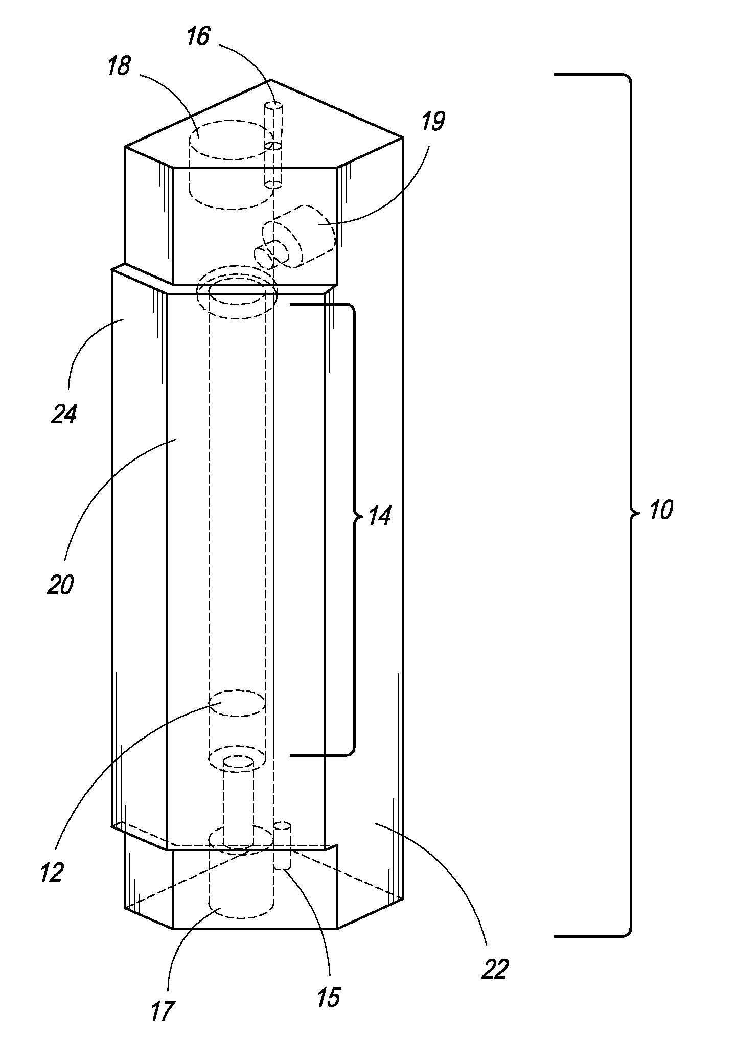
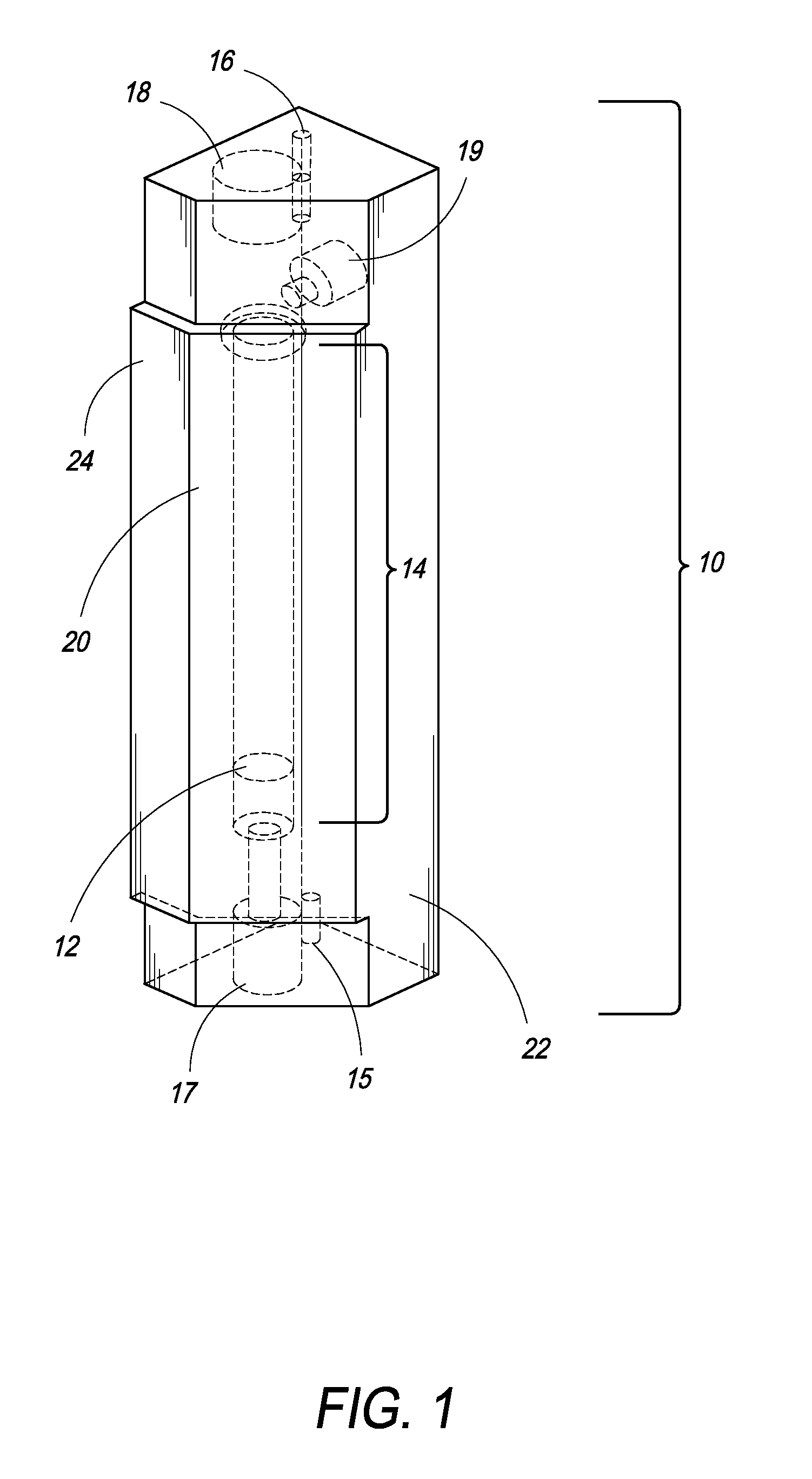
[0028]In one embodiment, the present invention is directed towards an improved fluid flow, such as any gas or liquid, gauging device in the form of a light enhanced flow tube.

[0029]In one embodiment, the present invention is directed towards a flow tube encased in an acrylic block, said flow tube containing a float or “bobbin”, said bobbin being illuminated from the top in an effort to enhance visualization of the bobbin, thereby enabling the user to make more accurate flow readings. The illumination is supplied via a light emitting diode (LED) or other light source and shines down from the top of the tube onto the bobbin. In one embodiment, the bobbin is spherical and of a reflective material so as to enhance visualization when illuminated from above. The prismatic effect of the acrylic block flow tube combined with the illumination of the bobbin allow for clearer visualization of the bobbin level and therefore more accurate flow readings, especially in low light conditions. The co...


PUM


Abstract

An improved fluid flow gauging device includes a light enhanced acrylic block flow tube to optimize visualization of pressure readings. An LED or other light source is fitted to the top of the flow tube and illuminates a float or bobbin from above to provide more accurate readings, especially in low light conditions such as modern operating rooms. In addition, the light enhanced flow tube provides a mechanical backup in the case of failure of newer electronic systems and visually matches the graphical flow display, simultaneously providing a double-check of the electronic system.

Description

CROSS REFERENCE OF THE INVENTION[0001]The present invention relies on U.S. Provisional Application No. 61 / 252,269, filed on Oct. 16, 2009, for priority, and incorporates the specification and drawings of this application by reference in its entirety.FIELD OF THE INVENTION[0002]The present invention relates to gas and liquid flow gauging devices. More particularly, the present invention relates to a light enhanced flow tube with a bobbin used as a measure of flow in anesthesia systems.BACKGROUND OF THE INVENTION[0003]Historically, transparent tubes containing a float or “bobbin” have been used as a means of measuring flow in gas and liquid systems. Visually observing the level of the bobbin alongside scaled markings on a plastic strip adjacent to the tube or printed on the walls of the tube itself, enables users to accurately gauge the flow of gas or liquid being applied to the system. Traditionally, such gauging devices have utilized an elongated illumination source positioned behin...

Claims


Application Information

Patent Timeline
IPC IPC(8): G01F1/22
CPCG01F23/64A61M16/0051A61M16/01A61M16/022A61M16/024A61M16/101A61M16/22A61M2205/584A61M2205/587A61M2209/084G01F1/22A61B50/10A61G12/001
Inventor BLUEMNER, ERIK J.KOSMOPOULOS, GEORGE P.
Owner SPACELABS HEALTHCARE INC
Why Eureka
Try Eureka