Lightweight, low cost solar energy collector

a solar energy collector, low cost technology, applied in the direction of solar heat systems, heat collector mounting/support, light and heating apparatus, etc., can solve the problems of not using additional costly structure, neither such patent discloses a transparent tubular enclosure, etc., to achieve the effect of reducing the sag or deformation of the array of fibers, reducing the cost of installation, and increasing the stiffness of the enclosure tub

Inactive Publication Date: 2011-04-21
CALIFORNIA INST OF TECH +1
View PDF5 Cites 30 Cited by
  • Summary
  • Abstract
  • Description
  • Claims
  • Application Information

AI Technical Summary

Benefits of technology

[0015]The anchorplates are centrally fastened to circular endplates. These endplates also serve to seal the ends of a transparent thin film cylindrical enclosure tube, which functions as a housing. The enclosure tube may be seamless or may comprise one or more seams which enable the enclosure tube to be formed from a flat flexible sheet. Once sealed, raising the pressure of the gas (air) inside the enclosure tube increases the stiffness of the enclosure tube. With only a modest internal pressure the enclosure becomes structurally stable with the capability to provide a weather tight housing for the internal mirror, receiver and other components. In addition, the inflated enclosure is designed with endplates that impart a portion of their pressure load into the anchor plates and hence the reflector forming fibers. In this manner, tension is provided to the fibers without using additional costly structure.
[0016]Because of the tension, sag or deformation of the array of fibers can be minimized even in the presence of the gravitational load represented by the reflector sheet. As tension is increased, deformation of both fiber and reflector is reduced and the reflector is even further constrained to follow the specific parabolic contour defined by the array of fiber-locating holes.

Problems solved by technology

Also, neither such patent discloses a transparent tubular enclosure that is pressurized to generate the tension in the fibers.

Method used


Image

  • Lightweight, low cost solar energy collector
  • Lightweight, low cost solar energy collector
  • Lightweight, low cost solar energy collector

Examples


first embodiment

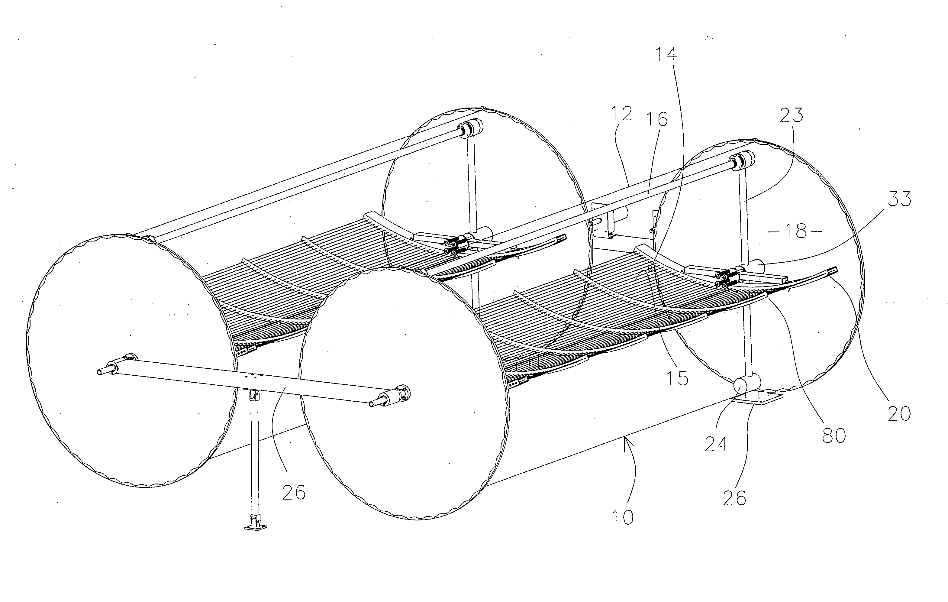
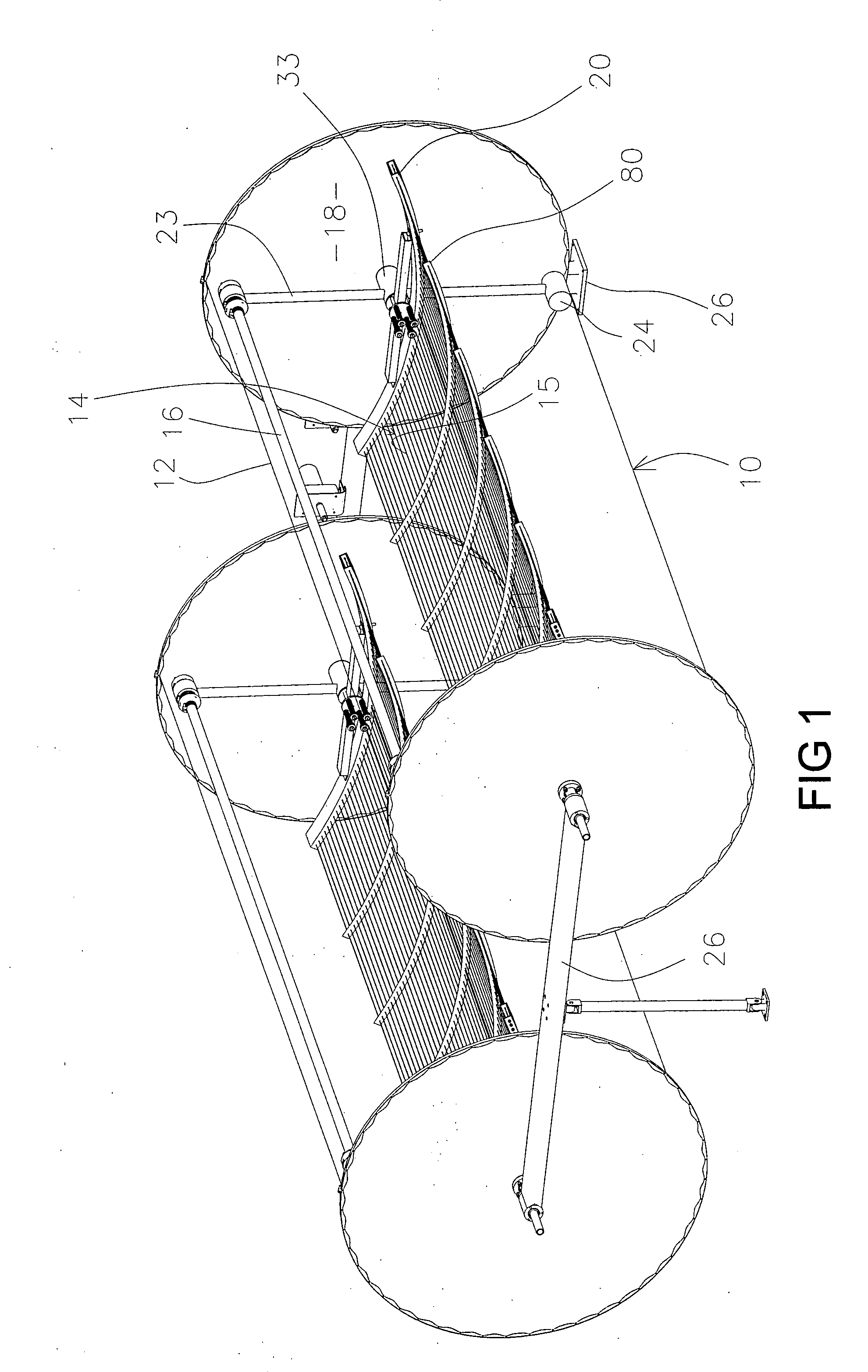
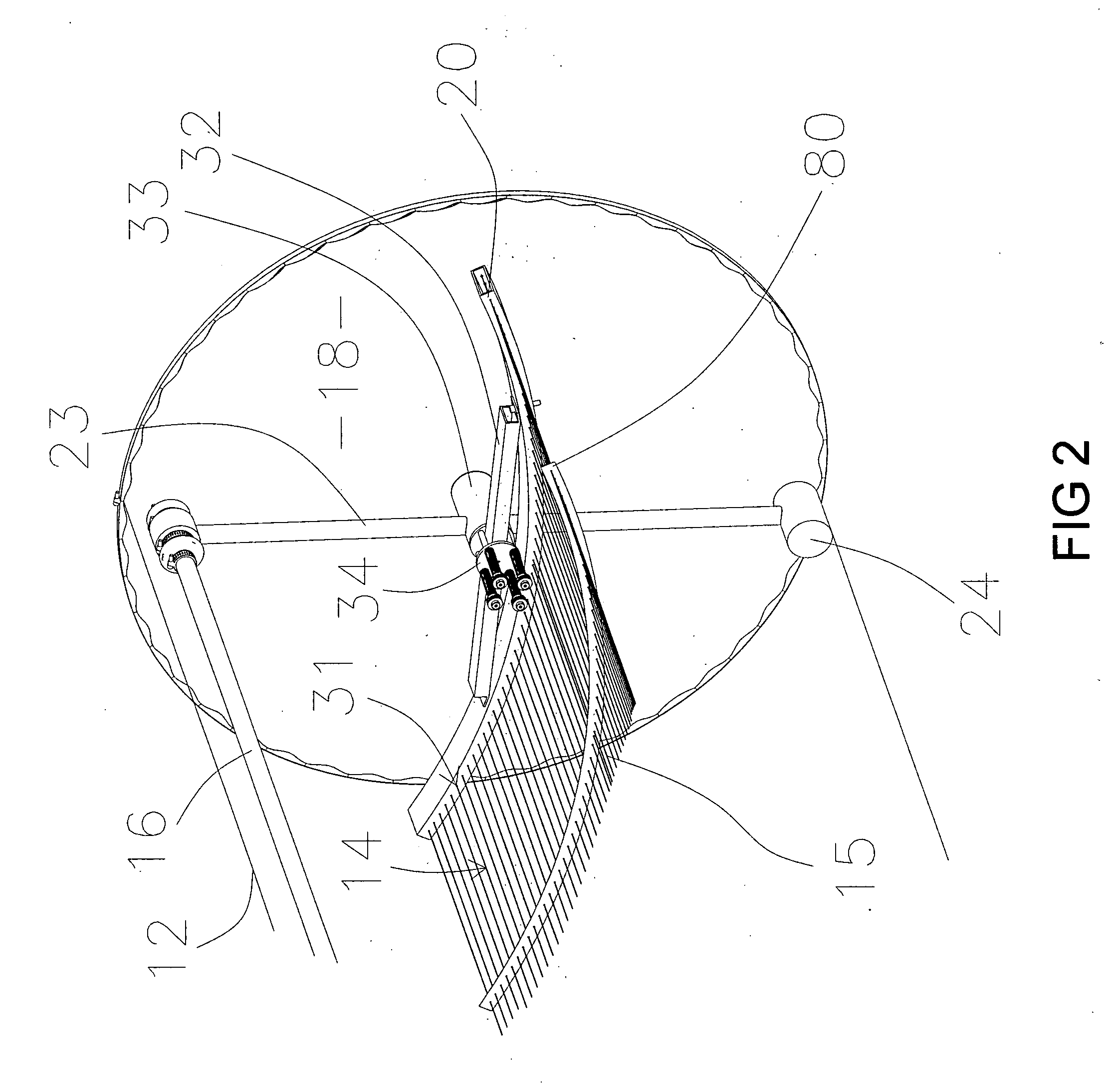
[0041]FIGS. 3 and 4 illustrate two embodiments used to secure anchorplate 20 to the hub 33. The first embodiment, shown in FIG. 3 utilizes springs to enhance axial compliance between the reflector assembly and transparent enclosure tube assembly. As shown therein, four symmetrically located shoulder bolts 28 extend through a pair of spaced anchorplate hubs 34 which are welded to the anchorplate crossbar 32. Each shoulder bolt 28 supports a corresponding helical spring 25 between hub 34 and a retainer 30. This arrangement precisely positions the anchorplate 20 relative to the hub 33 in all directions and rotations except along the hub axis. In the direction of the hub axis, the compliance of the helical springs 25 allow the anchorplate 20 to attain an optimal position relative to the hub 33 for maintaining string tension under a variety of the pressure and thermal loadings.

second embodiment

[0042]The second embodiment, shown in FIG. 4 depends upon an endplate 18 and or strings 15 and or enclosure tube 12 to provide axial compliance between the reflector assembly and tube assembly. As shown therein, the anchorplate 20 is attached to the hub 33 via a pinned and bolted joint. The pins 27 precisely position the anchorplate 20 relative to the hub 33 in all directions and rotations. The bolts 29 transfer loads from the anchorplate 20 to the hub 33.

[0043]FIGS. 5 and 6 illustrate the manner in which the hub 33 is attached and sealed from air leakage to the endplate 18. FIG. 5 provides a cross section view of the hub 33 to endcap 18 interface. As shown therein, the hub 33, is reduced in diameter to provide a shoulder 41 for axial positioning and sealing against the endcap 18. A gasket 39 is provided to ensure the seal and provide a soft interface with the endcap 18. A bolt ring 20 and gasket 42 are located on the outside of the collector enclosure. Bolts 43 secure the bolt ring...


PUM


Abstract

A lightweight solar concentrator of the reflecting parabolic or trough type is realized via a thin reflecting film, an inflatable structural housing and tensioned fibers. The reflector element itself is a thin, flexible, specularly-reflecting sheet or film. The film is maintained in the parabolic trough shape by means of a plurality of tensioned fibers arranged to be parallel to the longitudinal axis of the parabola. Fiber ends are terminated in two spaced anchorplates, each containing a plurality of holes, which lie on a desired parabolic contour. In a preferred embodiment, these fibers are arrayed in pairs with one fiber contacting the front side of the reflecting film and the other contacting the back side of the reflecting film. The reflective surface is thereby slidably captured between arrays of fibers, which control the shape, and position of the reflective film. Gas pressure in the inflatable housing generates fiber tension to achieve a truer parabolic shape. A plurality of bridges and or retention clips may be employed in certain embodiments to maintain the position of the reflective surface relative to the fibers.

Description

CROSS-REFERENCE TO CORRESPONDING APPLICATIONS[0001]This application takes priority from provisional patent application Ser. No. 60 / 412,518 filed on Sep. 20, 2002 and from utility patent application Ser. No. 10 / 601,923 filed on Jun. 19, 2003.ORIGIN OF THE INVENTION[0002]The invention described herein was made in the performance of work under a NASA contract, and is subject to the provisions of public law 96-517 (35 USC 202) in which the contractor has elected to retain title.BACKGROUND OF THE INVENTION[0003]1. Technical Field[0004]The present invention relates generally to the field of solar collectors having a parabolic trough to collect and concentrate solar energy. The invention pertains more specifically to an extremely lightweight and low cost parabolic trough solar collector.[0005]2. Background Art[0006]Parabolic trough technology is currently the most advanced solar thermal electric generating technology. This is primarily due to nine large commercial-scale solar power plants,...

Claims


Application Information

Patent Timeline
Patent Type & Authority Applications(United States)
IPC IPC(8): F24J2/46F24J2/12F24S23/71
CPCF24J2/145F24J2/5241Y02E10/47Y02E10/45F24J2/541F24S23/745F24S30/425F24S25/50F24S2030/15
Inventor HOCHBERG, ERIC B.COSTEN, MICHAEL K.
Owner CALIFORNIA INST OF TECH
Why Eureka
Try Eureka