Automatic switching valve with alarm

a technology of automatic switching valve and alarm, which is applied in the direction of gas/liquid distribution and storage, combustion process, lighting and heating apparatus, etc., can solve the problem of unexpected depletion of the reserve container

Active Publication Date: 2011-04-21
CAVAGNA GROUP
View PDF17 Cites 15 Cited by
  • Summary
  • Abstract
  • Description
  • Claims
  • Application Information

AI Technical Summary

Benefits of technology

[0007]According to one aspect, a gas pressure sensor assembly for a gas regulator is provided. The gas regulator includes a plurality of selectable inlets, an outlet and a gauge. Each inlet is configured to receive pressurized gas from a different one of a plurality of associated pressurized gas storage containers. The outlet supplies gas to an associated appliance. The gauge senses a gas pressure in a selected inlet corresponding to the associated pressurized gas storage container from which the inlet receives pressurized gas and visually indicates a pressure of that associated gas storage container. The gas pressure sensor assembly comprises a cooperating member and a sensing device. The cooperating member is at least partially housed within the gauge and includes a disc member rotatably responsive to a gas pressure in the selected inlet. The sensing device is releasably connected to the gauge. The sensing device is selectively actuated by movement of the disc member. The sensing device is configured to provide an audible signal to a user indicative of a generally empty status of the associated gas storage container connected to the selected inlet. The sensing device can be easily removed from a gauge of one gas regulator and releasably connected to a gauge of another gas regulator.

Problems solved by technology

Since the changeover is automatic and only occurs at spaced intervals and on an irregular basis, and may occur at night, the condition may go undetected for some time, leading to unexpected depletion of the reserve container.

Method used


Image

  • Automatic switching valve with alarm
  • Automatic switching valve with alarm
  • Automatic switching valve with alarm

Examples


Embodiment Construction

[0015]It should, of course, be understood that the description and drawings herein are merely illustrative and that various modifications and changes can be made in the structures disclosed without departing from the present disclosure. All references to direction and position, unless otherwise indicated, refer to the orientation of the gas regulator illustrated in the drawings and should not be construed as limiting the claims appended hereto.

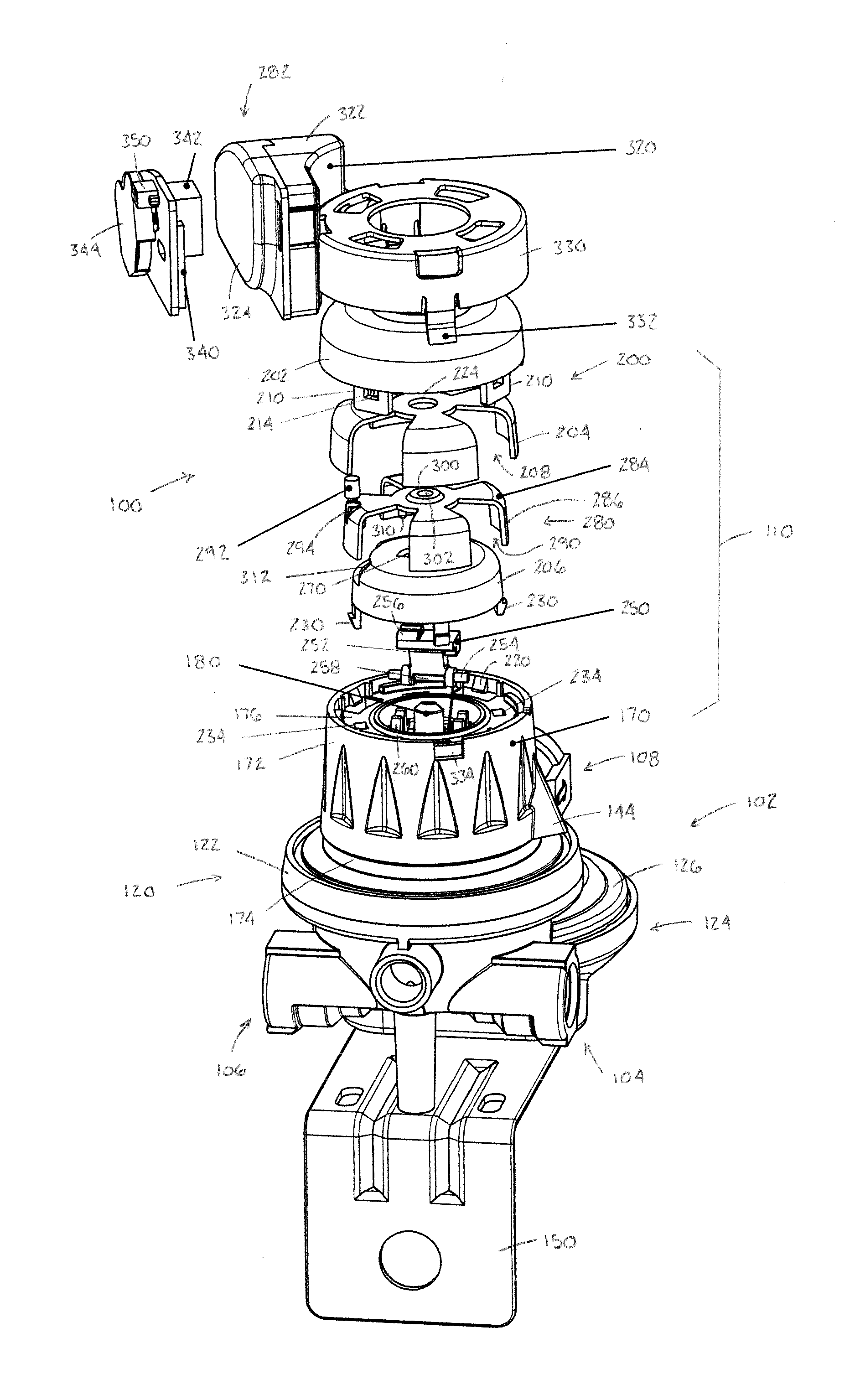
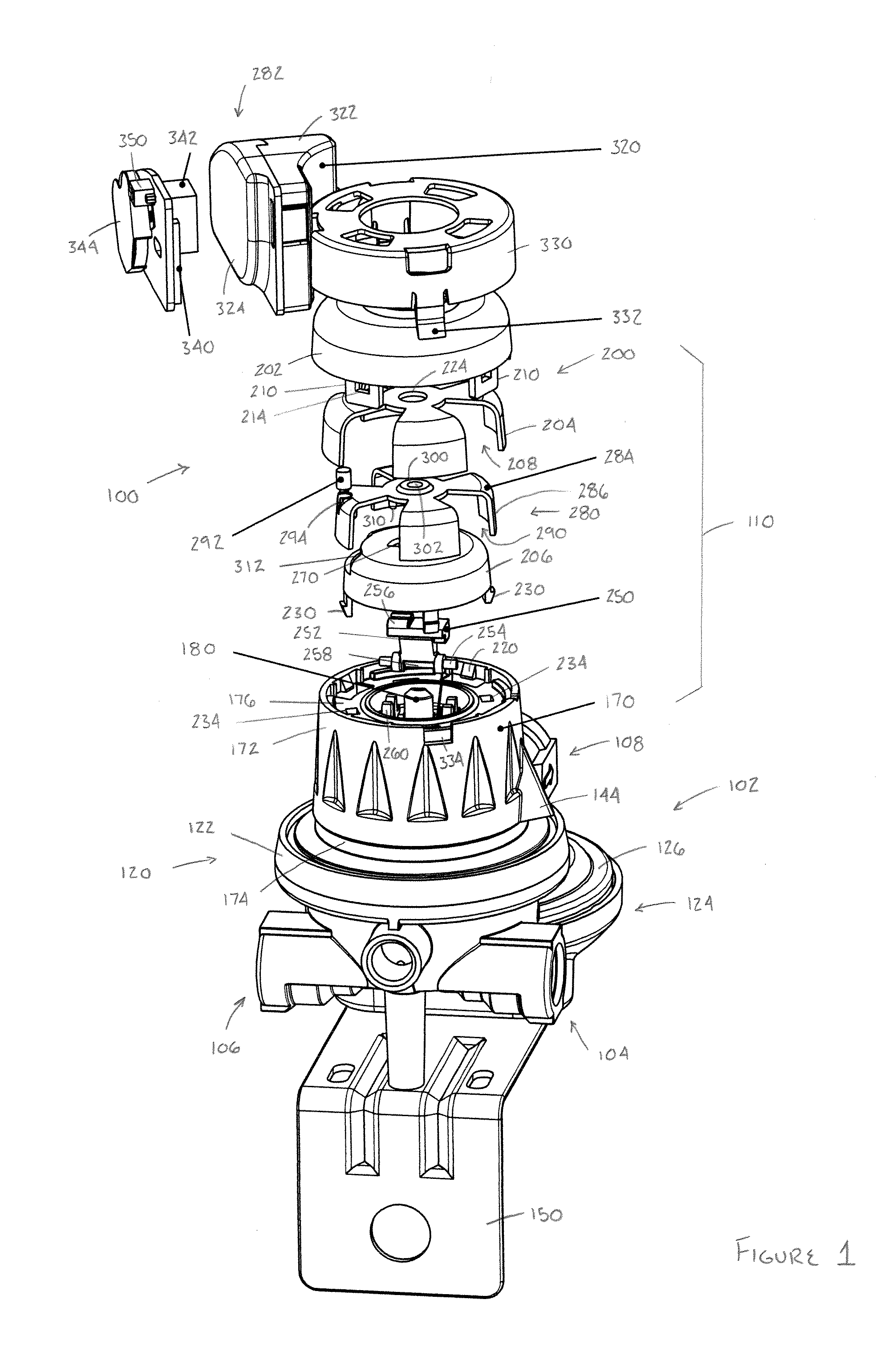
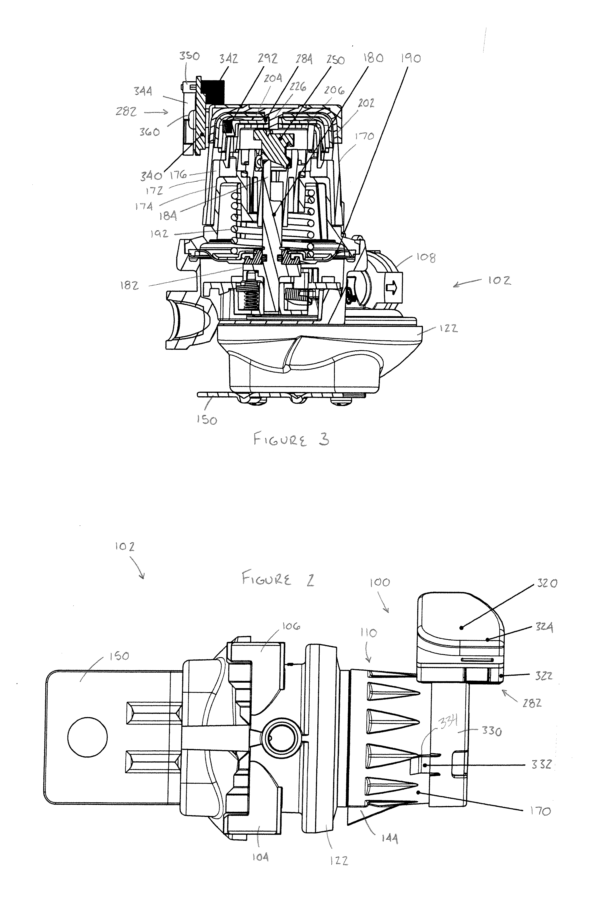
[0016]Referring now to drawings, wherein like numerals refer to like parts throughout the several views, FIGS. 1-4 illustrate a gas pressure sensor assembly 100 for a gas regulator 102, such as a two-stage LP gas regulator. The gas regulator 102 includes a plurality of selectable inlets (two inlets 104, 106 are shown), an outlet 108 and a gauge 110. Each inlet is configured to receive pressurized gas from a different one of a plurality of pressurized gas storage containers 112, 114 (FIG. 4). One of the gas storage containers is typically refer...


PUM


Abstract

A gas pressure sensor assembly for a gas regulator includes a plurality of selectable inlets, an outlet and a gauge. Each inlet is configured to receive pressurized gas from a different one of a plurality of associated pressurized gas storage containers. The outlet supplies gas to an associated appliance. The gauge senses a gas pressure in a selected inlet corresponding to the associated pressurized gas storage container from which the inlet receives pressurized gas and visually indicates a pressure of that associated gas storage container. The gas pressure sensor assembly includes a cooperating member and an sensing device. The cooperating member is at least partially housed within the gauge and includes a disc member rotatably responsive to a gas pressure in the selected inlet. The sensing device is releasably connected to the gauge. The sensing device is selectively actuated by movement of the disc member. The sensing device is configured to provide an audible signal to a user indicative of a generally empty status of the associated gas storage container connected to the selected inlet. The sensing device can be easily removed from a gauge of one gas regulator and releasably connected to a gauge of another gas regulator.

Description

BACKGROUND[0001]Exemplary embodiments herein relate to pressure-sensing and indicating devices for gas systems and, more particularly, to a removable indicator / alarm device for a gas regulator for at least one pressurized gas source such as an L.P. gas tank.[0002]Gas regulators are widely known and used to provide gas at a stepped-down pressure. One type of gas regulator is an automatic changeover two-stage LP gas regulator, such as those made by Cavagna of Italy, as well as other manufacturers. Automatic changeover gas regulators typically comprise a high-pressure changeover regulator and a low-pressure regulator. The high-pressure changeover regulator includes two inlets for receiving gas from two separate pressurized containers, reduces the gas pressure to a first predetermined level, and transmits that gas to the low-pressure regulator. The low-pressure regulator further reduces the gas pressure to a predetermined level prior to conveying the gas through an outlet to, for exampl...

Claims


Application Information

Patent Timeline
Patent Type & Authority Applications(United States)
IPC IPC(8): F16K37/00
CPCF23K2900/05001F23K5/007Y10T137/2567Y10T137/8175Y10T137/8326Y10T137/8359
Inventor CAVAGNA, SAVIO
Owner CAVAGNA GROUP
Why Eureka
Try Eureka