Medical imaging system and patient positioning system including a movable transport belt

a technology of medical imaging and positioning system, which is applied in the field of patient positioning and imaging system, can solve the problems of affecting image quality, affecting image quality, and affecting image quality,

Inactive Publication Date: 2011-04-21
GENERAL ELECTRIC CO
View PDF10 Cites 20 Cited by
  • Summary
  • Abstract
  • Description
  • Claims
  • Application Information

AI Technical Summary

Problems solved by technology

However, conventional multi-modality imaging systems may suffer from certain problems.
However, when the imaging pallet is extended into the bore, the imaging pallet may sag due to a weight of the patient.
Such sagging may adversely affect the images of the ROI and may also adversely affect any processing of the data to merge the different images.
However, the thickened imaging pallet may absorb more energy from the imaging system when an image of the ROI is obtained.
This attenuation may distort or reduce the quality of the image.
Furthermore, increasing a size of the imaging pallet may limit the ability of scanning detectors to move about the patient.
Also, depending upon the imaging modality being used, certain geometries of the imaging pallet may cause artifacts of the images.
However, since the imaging pallet moves with the patient when the patient is moved between the different FOVs, it is difficult to change the geometry of the imaging pallet that supports the ROI of the patient.

Method used


Image

  • Medical imaging system and patient positioning system including a movable transport belt
  • Medical imaging system and patient positioning system including a movable transport belt
  • Medical imaging system and patient positioning system including a movable transport belt

Examples


Embodiment Construction

The foregoing summary, as well as the following detailed description of certain embodiments of the present invention, will be better understood when read in conjunction with the appended drawings. As used herein, an element or step recited in the singular and proceeded with the word “a” or “an” should be understood as not excluding plural of said elements or steps, unless such exclusion is explicitly stated. Furthermore, references to “one embodiment” or “an embodiment” of the present invention are not intended to be interpreted as excluding the existence of additional embodiments that also incorporate the recited features. Moreover, unless explicitly stated to the contrary, embodiments “comprising” or “having” an element or a plurality of elements having a particular property may include additional elements not having that property.

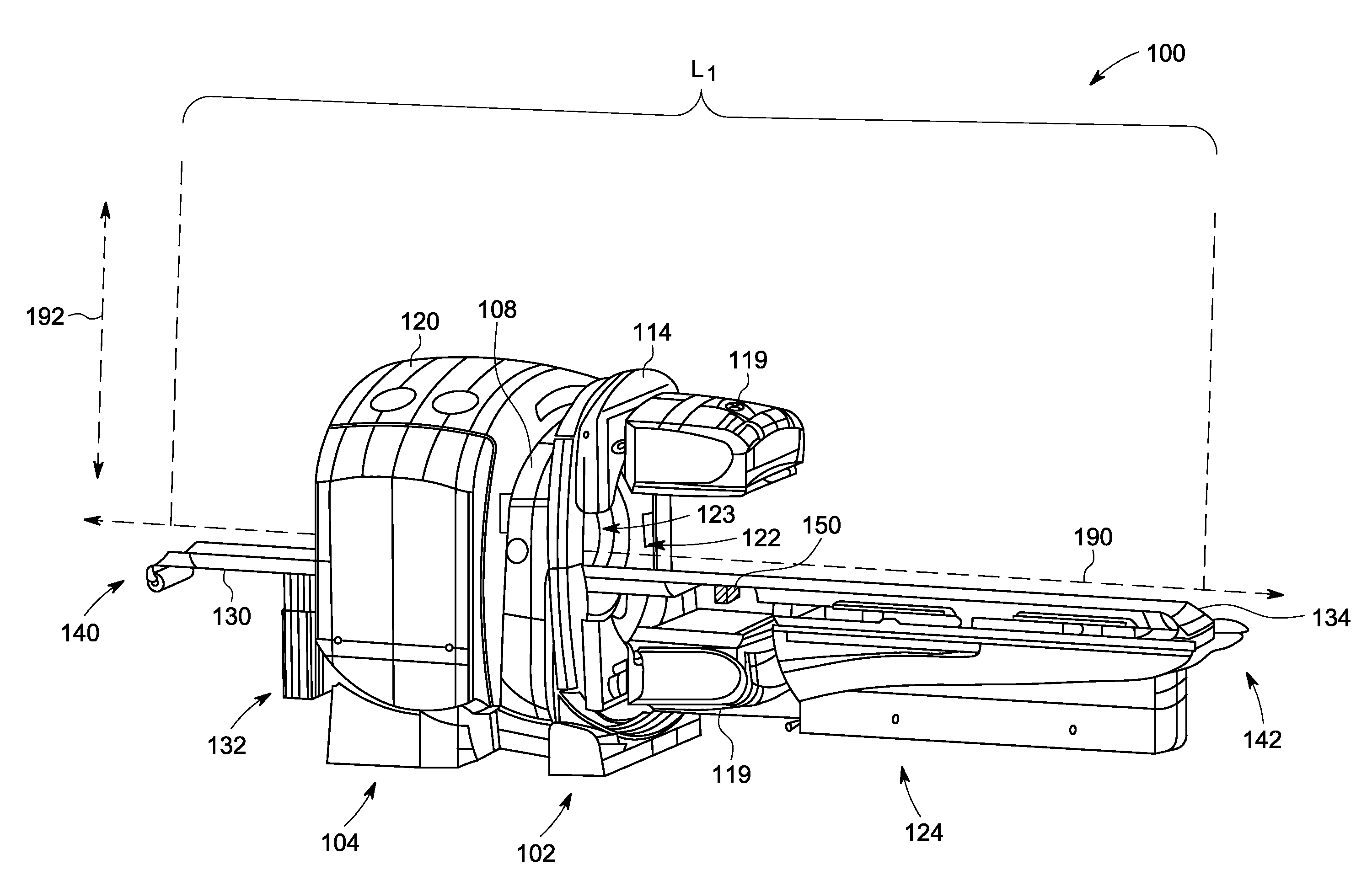
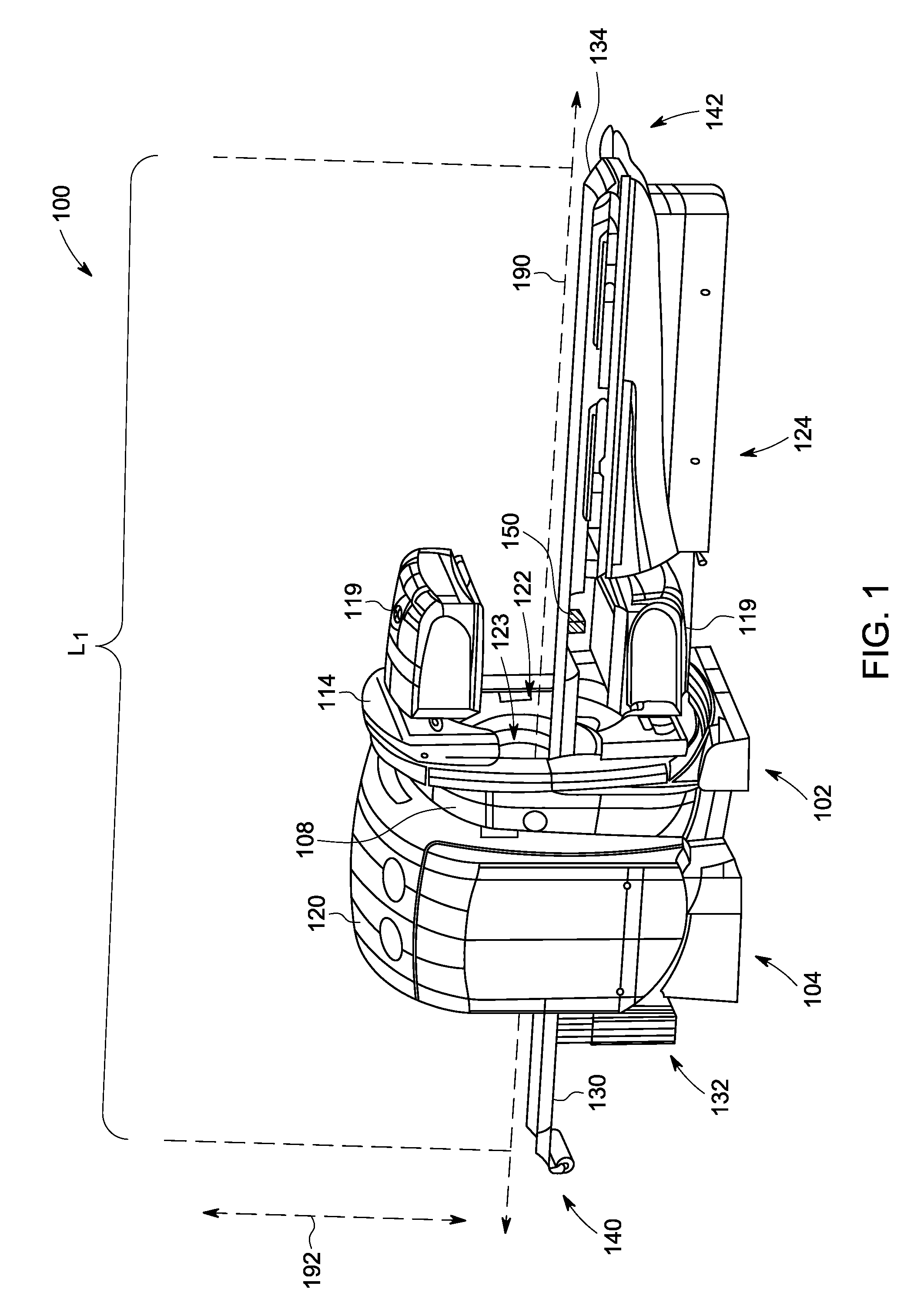
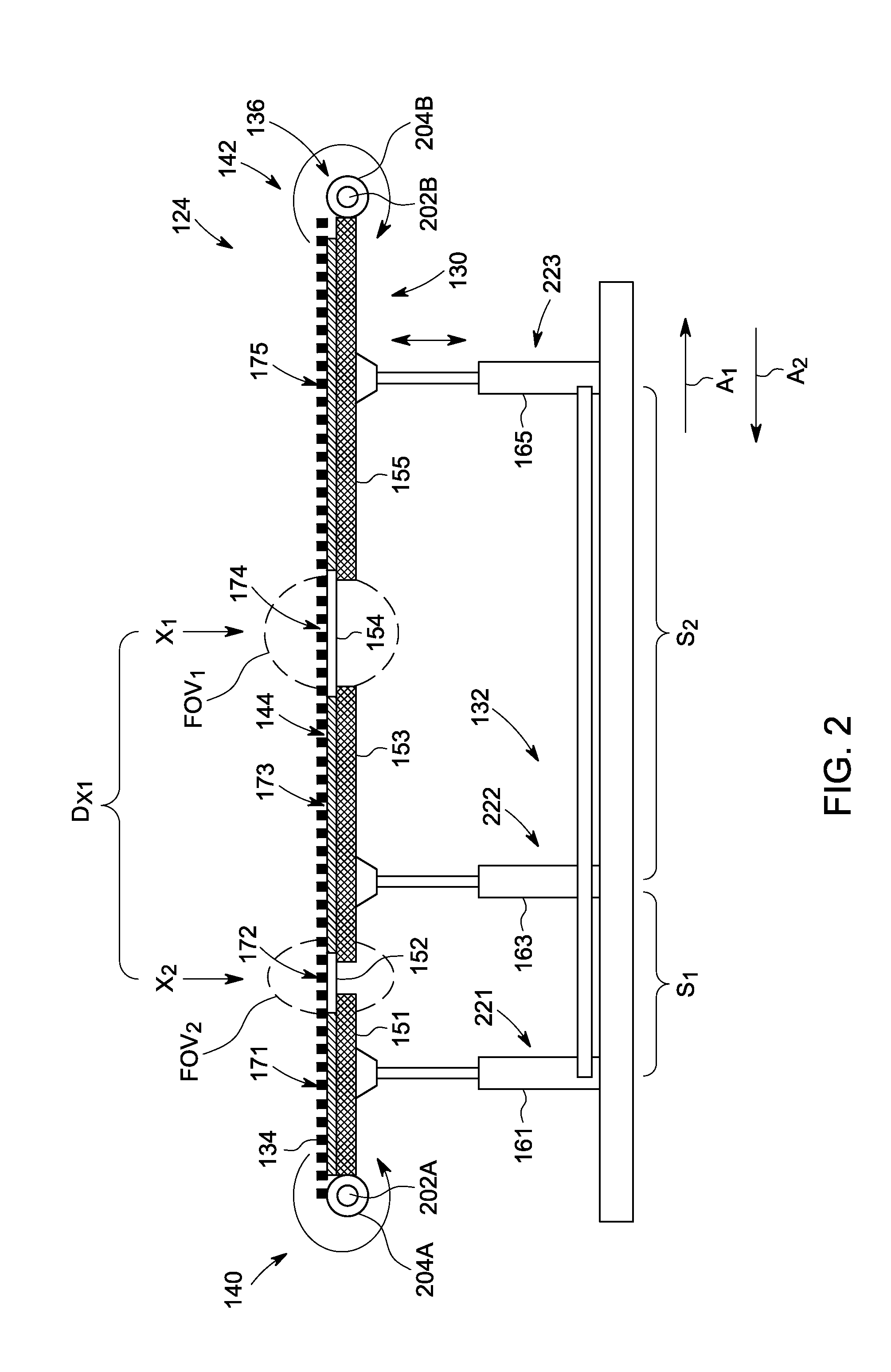
Various embodiments of the invention provide an imaging system 100 as shown in FIG. 1. The imaging system 100 may be any type of imaging system, includi...


PUM


Abstract

A medical imaging system for imaging a region of interest (ROI) in a patient. The imaging system includes an imaging modality unit having a field of view (FOV) and an examination platform. The examination platform has a pair of opposite ends and a platform surface extending therebetween along an examination axis. The platform surface extends into the FOV. The imaging system also includes a patient transport belt that is supported by the examination platform and extends along the platform surface between the ends of the examination platform. The imaging system also includes a motor that is operatively coupled to and configured to move the transport belt along the platform surface in a direction along the examination axis. The motor moves the transport belt so that a predetermined portion of the transport belt is within the FOV.

Description

BACKGROUND OF THE INVENTIONThe subject matter disclosed herein relates generally to patient positioning and imaging systems and more particularly, to imaging systems capable of moving a patient between different axial positions to scan the patient.Multi-modality imaging systems can scan a region of interest (ROI) of a patient using different imaging modalities. For example, multi-modality imaging systems may include Computed Tomography (CT), Magnetic Resonance Imaging (MRI), Positron Emission Tomography (PET), radiography, and / or Single Photon Emission Computed Tomography (SPECT) imaging systems. In these multi-modality imaging systems, the different modality units have respective field of views (FOVs) at different axial locations. During operation, a patient is moved to a first FOV where an image of the ROI is obtained and then moved to a second FOV where another image of the ROI is obtained. A doctor or medical technician (or the system) may then merge the data of the plurality of...

Claims


Application Information

Patent Timeline
Patent Type & Authority Applications(United States)
IPC IPC(8): A61B5/05A61B6/04
CPCA61B6/0471A61B6/508A61B6/547A61B6/469
Inventor BIRMAN, YOSSI
Owner GENERAL ELECTRIC CO
Why Eureka
Try Eureka