Uterus-manipulator

a technology of manipulators and uterus, which is applied in the field of microinvasive medical instruments, can solve problems such as injury risk, and achieve the effects of minimizing injury risk, small volume, and small cross-section

Active Publication Date: 2011-04-21
KARL STORZ GMBH & CO KG
View PDF8 Cites 18 Cited by
  • Summary
  • Abstract
  • Description
  • Claims
  • Application Information

AI Technical Summary

Benefits of technology

[0009]The end balloon is inflatable or can be expanded by introducing a fluid and is therefore especially atraumatic. Even when the end balloon is in inflated or expanded state, or is filled with a fluid, and touches an organ from the inside or outside and exerts a force on said organ, this force, owing to the extensive and elastic skin or wall of the balloon, is distributed over such a great surface that only a minimum pressure occurs. Because of the suppleness of the balloon or of its wall, local pressure points are effectively avoided. Consequently the risk of injury is considerably lessened, especially when for example, as in the case of a uterus manipulator, a force is meant to be, and must be, exerted in order to move an organ.
[0011]A first channel, whose lumen at the distal end is connected with the inside of the end balloon, and a second channel, whose lumen at the distal end is connected with the inside of the supporting balloon, can be provided in or on the shaft. Through these two channels the end balloon and the supporting balloon can be inflated or expanded independently of one another or their sizes can be adjusted. Alternatively, a single channel can be provided that is connected with the interior spaces both of the end balloon and of the supporting balloon, in order to be able to fill both balloons with a fluid.
[0015]The instrument can comprise a joint between a proximal segment and a distal segment of the shaft, so that the end balloon and in certain cases the supporting balloon are positioned on the distal segment of the shaft. Thus, for example, after inserting the distal segment in the cervix and uterus, the uterus can be moved. This is often necessary or at least advantageous, among other cases, in laparoscopic procedures in the pelvic region and in the lower abdominal region. A force exerted by the uterus manipulator on the uterus is distributed over a wide area by the end balloon, which completely encloses the distal end of the shaft. This minimizes the risk of injury.
[0016]To reduce further the risk of injury, in particular upon inserting the instrument, all radii of curvature on the distal end of the shaft enclosed by the end balloon are equal to at least a fourth, or still better at least a third, of the diameter of the shaft or of the maximum measurement of the cross-section of the shaft. A hemispheric-shaped end of the shaft is particularly advantageous, where the radii of curvature correspond to the diameter of the shaft, which is in particular cylindrical in shape.

Problems solved by technology

Conventional uterine manipulators and other devices for insertion into the uterus or other body cavities comprise thin ends that, even when made of silicon or another soft material, make possible a pointed impact on the sensitive mucous membrane of the uterus or other organs and thus constitute a risk of injury.

Method used


Image

  • Uterus-manipulator
  • Uterus-manipulator

Examples


Embodiment Construction

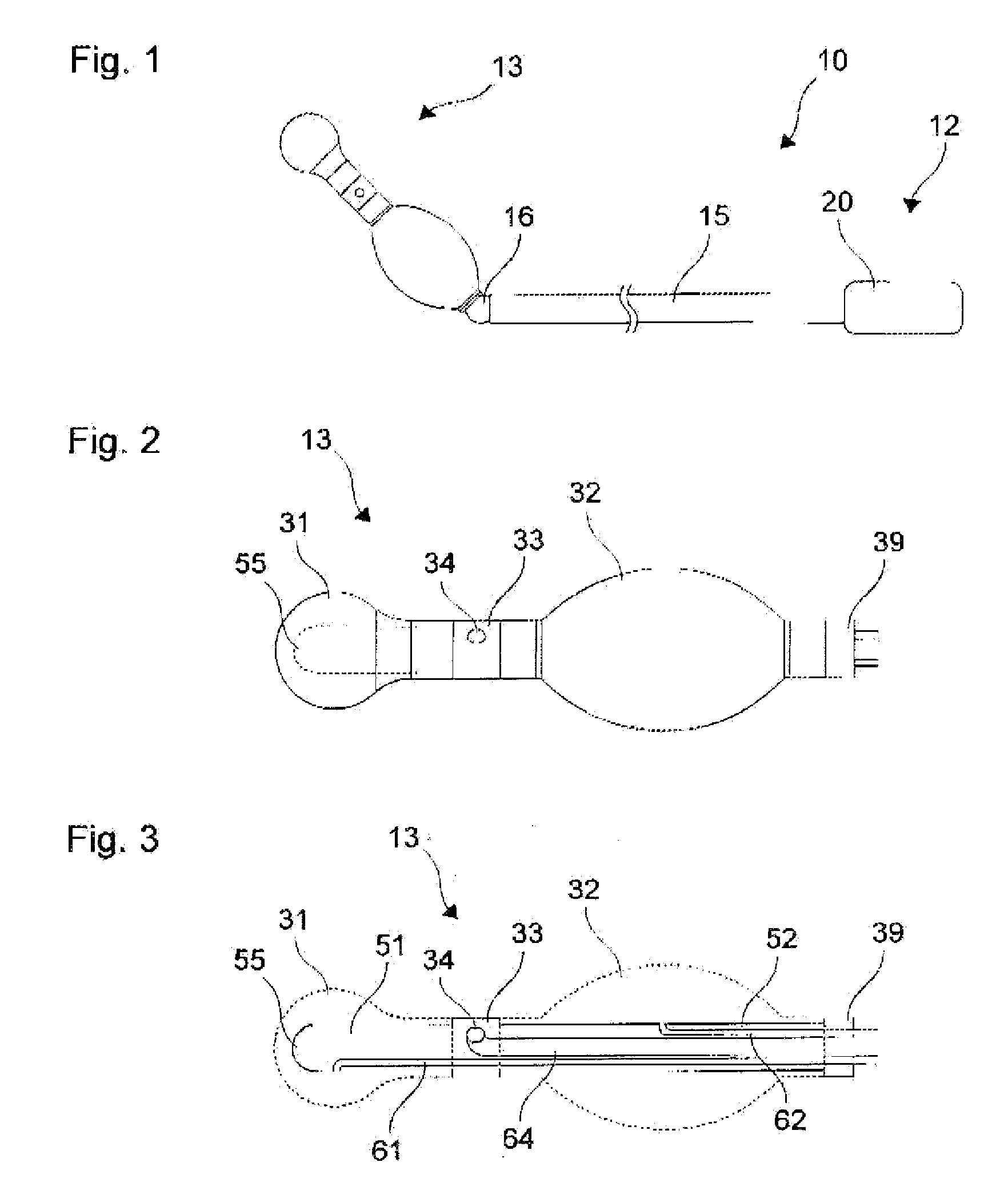
[0025]FIG. 1 shows a schematic depiction of a uterus manipulator 10 as an example of a micro-invasive medical instrument. The uterus manipulator 10 includes a proximal segment 12 and a distal segment 13 for insertion into the cervix and uterus. The uterus manipulator 10 includes a shaft 15, which extends from the proximal segment 12 to the distal segment 13. A joint 16 is positioned between a proximal segment and a distal segment of the shaft 15.

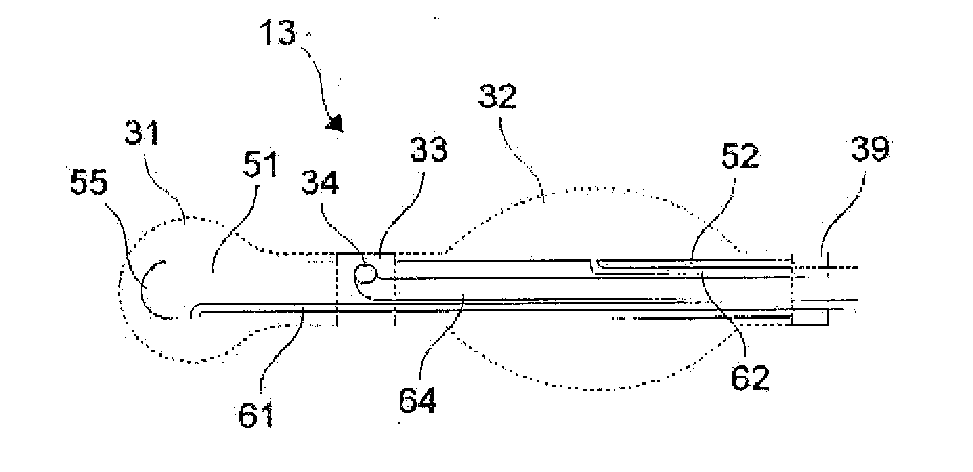
[0026]On the proximal end the shaft 15 is connected with a gripping device 20, which is shown only schematically in FIG. 1. The gripping device is configured for handling, guiding, and control of the uterus manipulator 10 and can include properties that clearly diverge from the schematic depiction in FIG. 1. The distal segment 13 of the uterus manipulator 10 is described in greater detail hereinafter with reference to FIGS. 2 and 3. The optional joint 16 is configured for an anteversion and / or retroversion of the uterus by an angle that can ...


PUM


Abstract

A micro-invasive medical instrument includes a shaft and an end balloon on a distal end of the shaft, where the end balloon completely encloses the distal end of the shaft.

Description

CROSS-REFERENCE TO RELATED APPLICATIONS[0001]The present application claims priority of German patent application No. 10 2009 049 169.4 filed on Oct. 12, 2009.FIELD OF THE INVENTION[0002]The present invention relates to a micro-invasive medical instrument, in particular a uterus manipulator.BACKGROUND OF THE INVENTION[0003]U.S. Pat. No. 5,104,377 describes a device to insert fluids or other instruments into the uterus. The device includes two balloons for positioning inside or outside the cervix uteri.[0004]In U.S. Pat. No. 5,643,311 a uterus manipulator is described whose distal section can be moved by means of a joint or articulated linkage. The distal end comprises a soft silicon tip.[0005]Conventional uterine manipulators and other devices for insertion into the uterus or other body cavities comprise thin ends that, even when made of silicon or another soft material, make possible a pointed impact on the sensitive mucous membrane of the uterus or other organs and thus constitute...

Claims


Application Information

Patent Timeline
Patent Type & Authority Applications(United States)
IPC IPC(8): A61B17/42A61F2/958
CPCA61B17/4241A61B2017/00557A61B2017/0023
Inventor HAHN, MARTINDOLL, FRANKGRAF, ANNE-KATHRINSTECKELER, SVEN
Owner KARL STORZ GMBH & CO KG
Why Eureka
Try Eureka