
Uterus-manipulator

a technology of manipulators and uterus, which is applied in the field of microinvasive medical instruments, can solve problems such as injury risk, and achieve the effects of minimizing injury risk, small volume, and small cross-section

Active Publication Date: 2014-03-18
KARL STORZ GMBH & CO KG
View PDF9 Cites 2 Cited by
  • Summary
  • Abstract
  • Description
  • Claims
  • Application Information

AI Technical Summary

Benefits of technology

The design significantly reduces the risk of injury by distributing force evenly and allowing for controlled manipulation of organs, such as during laparoscopic procedures, while maintaining atraumatic properties.

Problems solved by technology

Conventional uterine manipulators and other devices for insertion into the uterus or other body cavities comprise thin ends that, even when made of silicon or another soft material, make possible a pointed impact on the sensitive mucous membrane of the uterus or other organs and thus constitute a risk of injury.

Method used


Image

  • Uterus-manipulator
  • Uterus-manipulator

Examples


Embodiment Construction

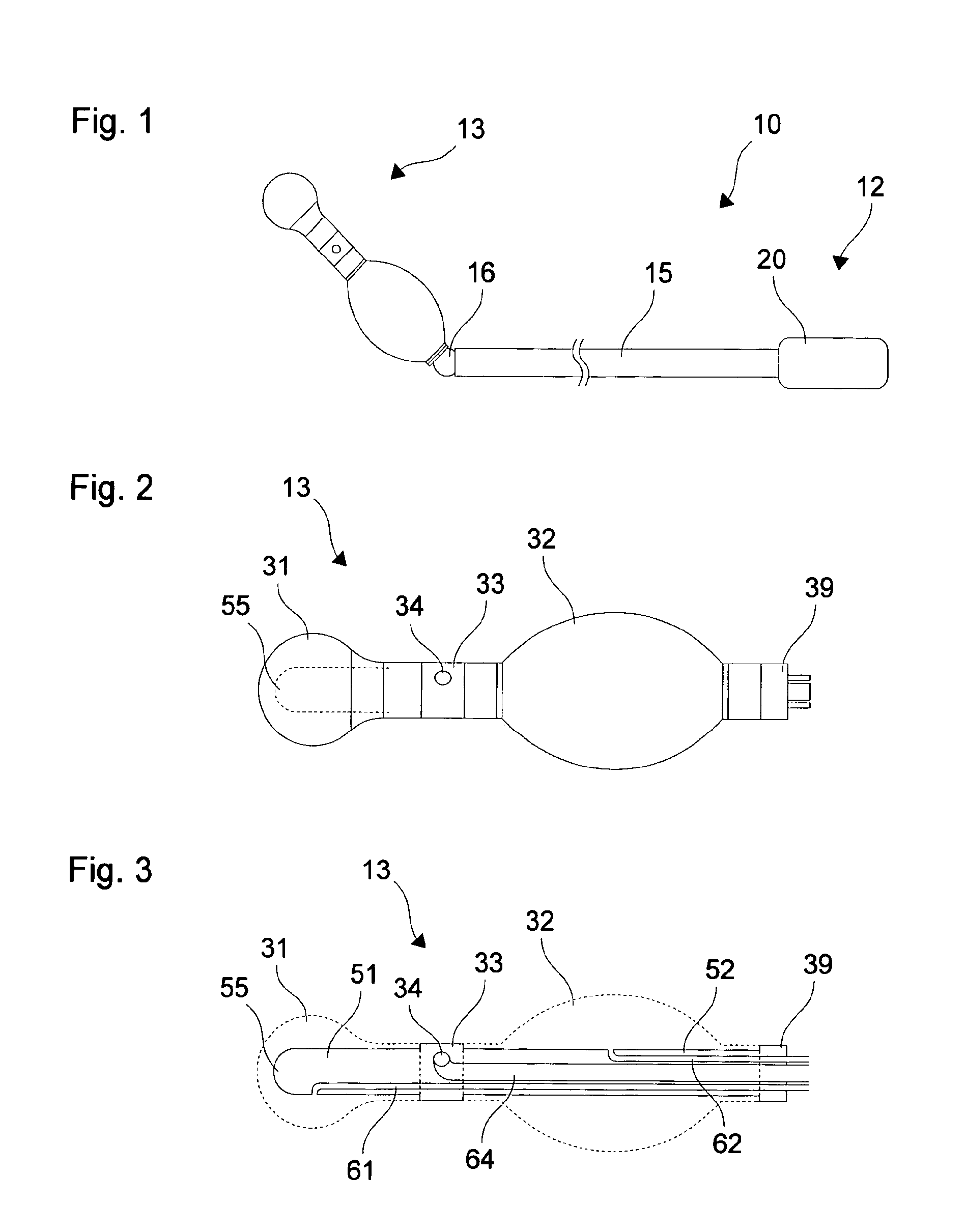
[0025]FIG. 1 shows a schematic depiction of a uterus manipulator 10 as an example of a micro-invasive medical instrument. The uterus manipulator 10 includes a proximal segment 12 and a distal segment 13 for insertion into the cervix and uterus. The uterus manipulator 10 includes a shaft 15, which extends from the proximal segment 12 to the distal segment 13. A joint 16 is positioned between a proximal segment and a distal segment of the shaft 15.

[0026]On the proximal end the shaft 15 is connected with a gripping device 20, which is shown only schematically in FIG. 1. The gripping device is configured for handling, guiding, and control of the uterus manipulator 10 and can include properties that clearly diverge from the schematic depiction in FIG. 1. The distal segment 13 of the uterus manipulator 10 is described in greater detail hereinafter with reference to FIGS. 2 and 3. The optional joint 16 is configured for an anteversion and / or retroversion of the uterus by an angle that can ...


PUM


Abstract

A micro-invasive medical instrument includes a shaft and an end balloon on a distal end of the shaft, where the end balloon completely encloses the distal end of the shaft.

Description

CROSS-REFERENCE TO RELATED APPLICATIONS[0001]The present application claims priority of German patent application No. 10 2009 049 169.4 filed on Oct. 12, 2009.FIELD OF THE INVENTION[0002]The present invention relates to a micro-invasive medical instrument, in particular a uterus manipulator.BACKGROUND OF THE INVENTION[0003]U.S. Pat. No. 5,104,377 describes a device to insert fluids or other instruments into the uterus. The device includes two balloons for positioning inside or outside the cervix uteri.[0004]In U.S. Pat. No. 5,643,311 a uterus manipulator is described whose distal section can be moved by means of a joint or articulated linkage. The distal end comprises a soft silicon tip.[0005]Conventional uterine manipulators and other devices for insertion into the uterus or other body cavities comprise thin ends that, even when made of silicon or another soft material, make possible a pointed impact on the sensitive mucous membrane of the uterus or other organs and thus constitute...

Claims


Application Information

Patent Timeline
Patent Type & Authority Patents(United States)
IPC IPC(8): A61F2/958A61B17/42
CPCA61B2017/00557A61B2017/0023A61B17/4241
Inventor HAHN, MARTINDOLL, FRANKGRAF, ANNE-KATHRINSTECKELER, SVEN
Owner KARL STORZ GMBH & CO KG
Learn More