Method and device for engaging a clutch

a technology of a clutch and a method, which is applied in the direction of clutches, instruments, computing, etc., can solve the problems of occupants in vehicles, increased wear on the transmitting mechanical components, and a torque transmission between the drive unit and the clutch, so as to reduce the distance of the operating position, shorten the method of engaging the clutch, and reduce the effect of engagement speed

Inactive Publication Date: 2011-04-21
ROBERT BOSCH GMBH
View PDF15 Cites 2 Cited by
  • Summary
  • Abstract
  • Description
  • Claims
  • Application Information

AI Technical Summary

Benefits of technology

[0007]The advantage of the present invention lies in a shortened method for engaging the clutch, in particular for touch point adaptations, and nevertheless a gradual approach to the new unknown touch point of the clutch.
[0008]In another embodiment of the present invention, the clutch passes through various operating positions when engaging, and the course of the speed profile depends on at least one of the previously known touch point positions, in such a way that the engagement speed of the clutch in an operating position depends on the distance between the operating position and the at least one previously known touch point position. The engagement speed decreases in particular with a decrease in the distance of the operating position from the at least one previously known touch point position.
[0009]The technical background of this embodiment is that an excessively rapid approach to the unknown new touch point is prevented, and thus a jump in the torque transmission between the drive unit and the clutch is prevented. In addition to increased wear on the transmitting mechanical components, this could be noticeable for the occupants in a vehicle as an unpleasant jolt.
[0010]The advantage of this embodiment is in a shortened method for engaging the clutch, in particular for touch point adaptations, and nevertheless a slow approach to the new unknown touch point of the clutch.
[0011]In another embodiment, the clutch passes through various operating positions when the clutch is engaged, and the course of the speed profile depends on the distance between at least two of the previously known touch point positions in relation to one another.
[0012]The technical background is that the distances between the touch point positions ascertained in succession may deviate very greatly among one another, depending on the design of the clutch and the use conditions.

Problems solved by technology

Approaching the unknown new touch point too rapidly would result in a jump in the torque transmission between the drive unit and the clutch.
In addition to increased wear on the transmitting mechanical components, this could be noticeable for occupants in a vehicle as an unpleasant jolt.

Method used


Image

  • Method and device for engaging a clutch
  • Method and device for engaging a clutch
  • Method and device for engaging a clutch

Examples


Embodiment Construction

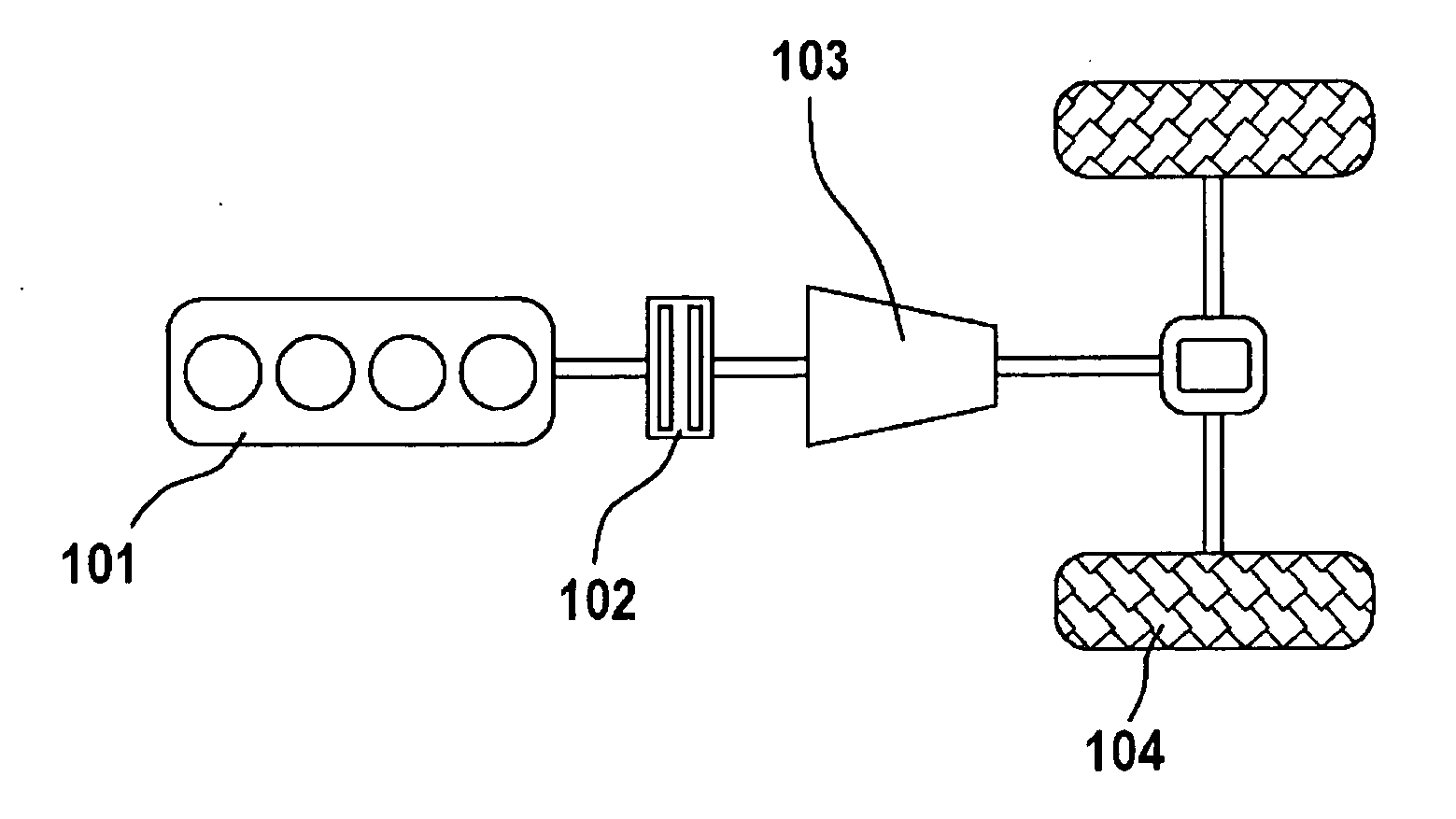
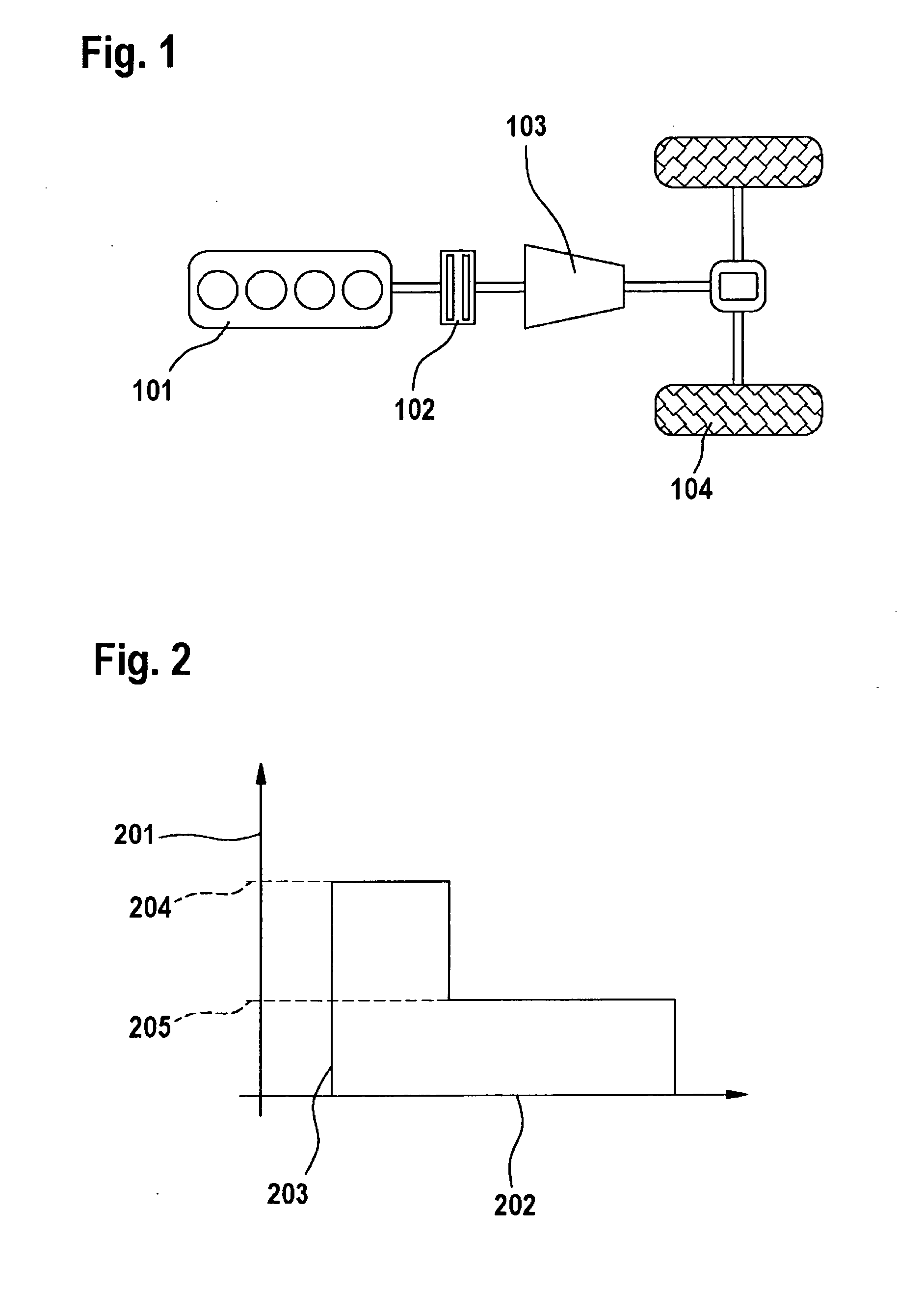
[0032]FIG. 1 shows a drive train of a vehicle. The drive train is composed of a drive unit 101, in particular an internal combustion engine, a clutch 102, a transmission 103, and a drive axle having drive wheels 104.

[0033]FIG. 2 shows a speed / time diagram, the speed being plotted on y-axis 201 and the time being plotted on x-axis 202. A two-phase speed profile is plotted in this diagram. The clutch begins to engage at point in time 203. The clutch is first engaged at first speed 204, and beyond a speed-changing position, the clutch is engaged further at a second speed 205.

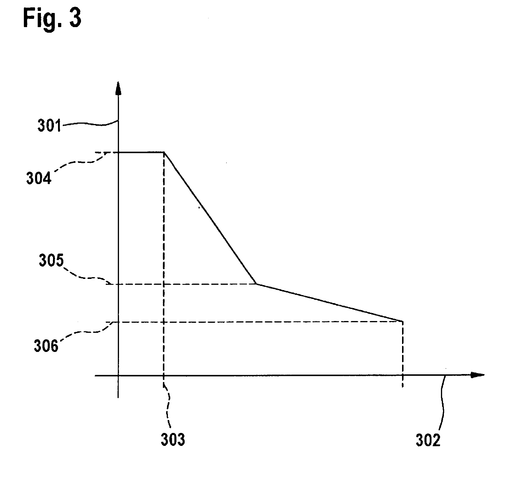
[0034]FIG. 3 shows a distance / time diagram. The distance traveled by the clutch is plotted on y-axis 301. The time is plotted on x-axis 302. In operating position 304, the clutch is in the disengaged state. At point in time 303, the clutch is engaged at a first speed up to the operating position of speed-changing position 305. The clutch is next engaged at a second speed up to new unknown touch point 306.

[0035]FIG....


PUM


Abstract

In a method for engaging a clutch having at least one previously known touch point position, the clutch is engaged according to a speed profile, the course of which depends on at least one of the previously known touch point positions.

Description

BACKGROUND OF THE INVENTION[0001]1. Field of the Invention[0002]The present invention relates to a device and a method for engaging a clutch.[0003]2. Description of Related Art[0004]Such a clutch is used in a drive train of a motor vehicle, for example. A drive train usually includes a drive unit, a transmission and a drive axle having drive wheels, a clutch often being situated between the drive unit and the transmission. The power of the drive unit is transmissible via the clutch to the transmission and thus to the drive axle and the drive wheels. The proportion of the power transmitted via the clutch to the transmission is controllable by disengaging and engaging the clutch. Published German patent document DE 195 40 921 describes a clutch with which disengaging and engaging are executed by a servo drive. A desired clutch torque is implemented by triggering the servo drive.BRIEF SUMMARY OF THE INVENTION[0005]The method and the device according to the present invention for engagin...

Claims


Application Information

Patent Timeline
Patent Type & Authority Applications(United States)
IPC IPC(8): F16D48/06
CPCF16D48/06F16D2500/10412F16D2500/50251F16D2500/70673F16D2500/70414F16D2500/70605F16D2500/70412
Inventor SEEL, ANDREAS
Owner ROBERT BOSCH GMBH
Why Eureka
Try Eureka