Multi-bit-per-cell flash memory device with non-bijective mapping

a multi-bit per-cell, flash memory technology, applied in error detection/correction, digital storage, instruments, etc., can solve the problems of increasing the number of voltage levels, affecting the reliability of flash memory, and affecting the performance of flash memory,

Active Publication Date: 2011-04-21
WESTERN DIGITAL ISRAEL LTD
View PDF47 Cites 41 Cited by
  • Summary
  • Abstract
  • Description
  • Claims
  • Application Information

AI Technical Summary

Problems solved by technology

These harmful physical processes corrupt the information stored in the flash cells.
Unfortunately, increasing the number of voltage levels that can be programmed in each flash cell has a negative effect both on the flash memory reliability and on the flash memory performance.
For example, as the number of voltage levels increases, the expected data retention time of the flash memory decreases and the expected number of available program / erase cycles decreases, resulting in a lower flash memory reliability.
Moreover, the read / write throughput of the flash memory becomes slower with the increase of the number of flash cell voltage levels.
Hence there is a tradeoff between the flash memory cost (the IBPC of the flash memory) and the reliability and performance of the flash memory.
However, it is not sufficient that the mapping function provide for a high IBPC.
This method incurs high encoder complexity.

Method used


Image

  • Multi-bit-per-cell flash memory device with non-bijective mapping
  • Multi-bit-per-cell flash memory device with non-bijective mapping
  • Multi-bit-per-cell flash memory device with non-bijective mapping

Examples


example 1

Computing the Capacity of Flash Memory 10 of FIG. 4

[0138]The programming and read voltage levels are: X=Y=[0 0.333 0.666 1] [Volts],

[0139]The flash memory suffers from an additive Gaussian noise with standard deviation σ=150 [mV],

[0140]Each programming level is programmed with equal probability:

[0141]P(Xi)=0.25 for i=1, 2, 3, 4

[0142]The transition probabilities are computed as follows:

P(YjXi)=Q(Yj-Xi-0.1667σ)-Q(Yj-Xi+0.1667σ)forj=2,3P(YjXi)=Q(Yj-Xi-0.1667σ)forj=1,4where,Q(x)=∫x∞12π-x2 / 2

[0143]Then the flash capacity is given by:

C=∑i=14∑j=14P(Xi)P(YjXi)log2(P(YjXi)∑k=14P(Xk)P(YjXk))=1.1612IBPC

example 2

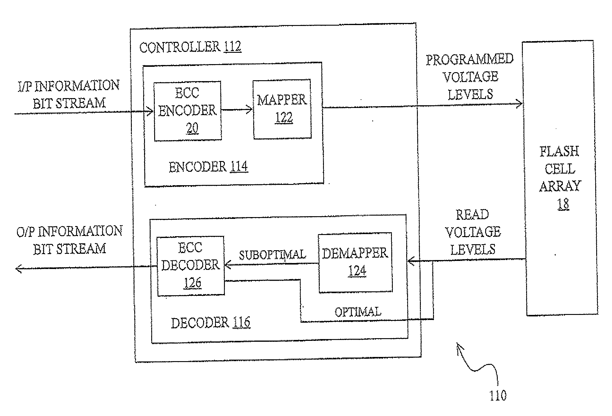
Computing the Capacity of Flash Memory 110 of FIG. 5, Embodiment of Tables 4 and 5:

[0144]The programming and read voltage levels are: X=Y=[0 0.5 1] [Volts],

[0145]The flash memory suffers from an additive Gaussian noise with standard deviation σ=150 [mV],

[0146]The non-bijective mapping induces the following non-uniform distribution over the programming voltage levels:

[0147]P(X)=[0.375 0.25 0.375]

[0148]The transition probabilities are computed as follows:

P(YjXi)=Q(Yj-Xi-0.25σ)-Q(Yj-Xi+0.25σ)forj=2P(YjXi)=Q(Yj-Xi-0.25σ)forj=1,3

[0149]Then the flash capacity is given by:

C=∑i=14∑j=14P(Xi)P(YjXi)log2(P(YjXi)∑k=14P(Xk)P(YjXk))=1.2224IBPC

Annex B: Formal Function-Related Definitions

[0150]Definition (one-to-one): A function ƒ is said to be one-to-one (injective) if and only if ƒ(x)=ƒ(y) implies x=y. Otherwise, the function is many-to-one: there exists at least one argument pair (x,y) such that x≠y and ƒ(x)=ƒ(y).

[0151]Definition (onto): A function ƒ from a set A to a set B is said to be onto(su...


PUM


Abstract

To store input data in a plurality of memory cells, a mapping function of bit sequences to physical parameter states of the cells is provided. The cells are programmed, in accordance with the mapping function, to store the input data, in a way that would store uniformly distributed data with a programming state distribution other than any native state distribution of the mapping function. To store input data in a single memory cell, a mapping function of bit sequences to states of a physical parameter of the cell, such that if uniformly distributed data were stored in a plurality of such memory cells then the states of the physical parameter of the cells would be distributed non-uniformly, is provided. The memory cell is programmed to store the input data in accordance with the mapping function.

Description

[0001]This patent application is a continuation-in-part of U.S. patent application Ser. No. 12 / 612,733, filed Nov. 5, 2009, which is a continuation of U.S. patent application Ser. No. 12 / 045,733, filed Mar. 11, 2008, now U.S. Pat. No. 7,643,342, issued Jan. 5, 2010, which is a divisional application of U.S. patent application Ser. No. 11 / 540,560, filed Oct. 2, 2006, now U.S. Pat. No. 7,388,781, that claimed the benefit of U.S. Provisional Patent Application No. 60 / 779,044, filed Mar. 6, 2006FIELD AND BACKGROUND OF THE INVENTION[0002]The technology described herein relates to the programming of flash memories, especially multi-bit-per-cell flash memories.[0003]A simplified block diagram of a Multi-Bit-Per-Cell (MBPC) flash memory device 10 is shown in FIG. 1. Specifically, the two components of flash memory device 10 that are illustrated in FIG. 1 are a flash controller 12 and a flash memory cell array 18.[0004]Flash controller 12 includes two blocks: an encoder block 14 that transla...

Claims


Application Information

Patent Timeline
Patent Type & Authority Applications(United States)
IPC IPC(8): G06F12/00G11C16/04
CPCG06F11/1072G11C11/5628G11C16/34G11C2211/5641G11C29/24G11C16/10G11C7/1006
Inventor SHARON, ERANALROD, IDAN
Owner WESTERN DIGITAL ISRAEL LTD
Why Eureka
Try Eureka