Exhaust gas recirculation valve device

a technology of exhaust gas and valve body, which is applied in the direction of spindle sealing, mechanical equipment, machines/engines, etc., can solve the problem that the sealing member cannot exhibit the sealing performance, and achieve the effect of improving the attachment of the sealing member to the housing

Inactive Publication Date: 2011-04-28
MITSUBISHI ELECTRIC CORP
View PDF15 Cites 45 Cited by
  • Summary
  • Abstract
  • Description
  • Claims
  • Application Information

AI Technical Summary

Benefits of technology

[0007]In accordance with the present invention, because the sealing member supported by the plug is disposed between the portion of the housing on the exhaust gas passage side of the bearing, and the valve shaft, the seal performance of the sealing member sealing surface between the

Problems solved by technology

Because the conventional exhaust gas recirculation valve device is constructed as above, a problem with the conventional exhaust gas recirculation valve device

Method used


Image

  • Exhaust gas recirculation valve device
  • Exhaust gas recirculation valve device
  • Exhaust gas recirculation valve device

Examples


embodiment 1

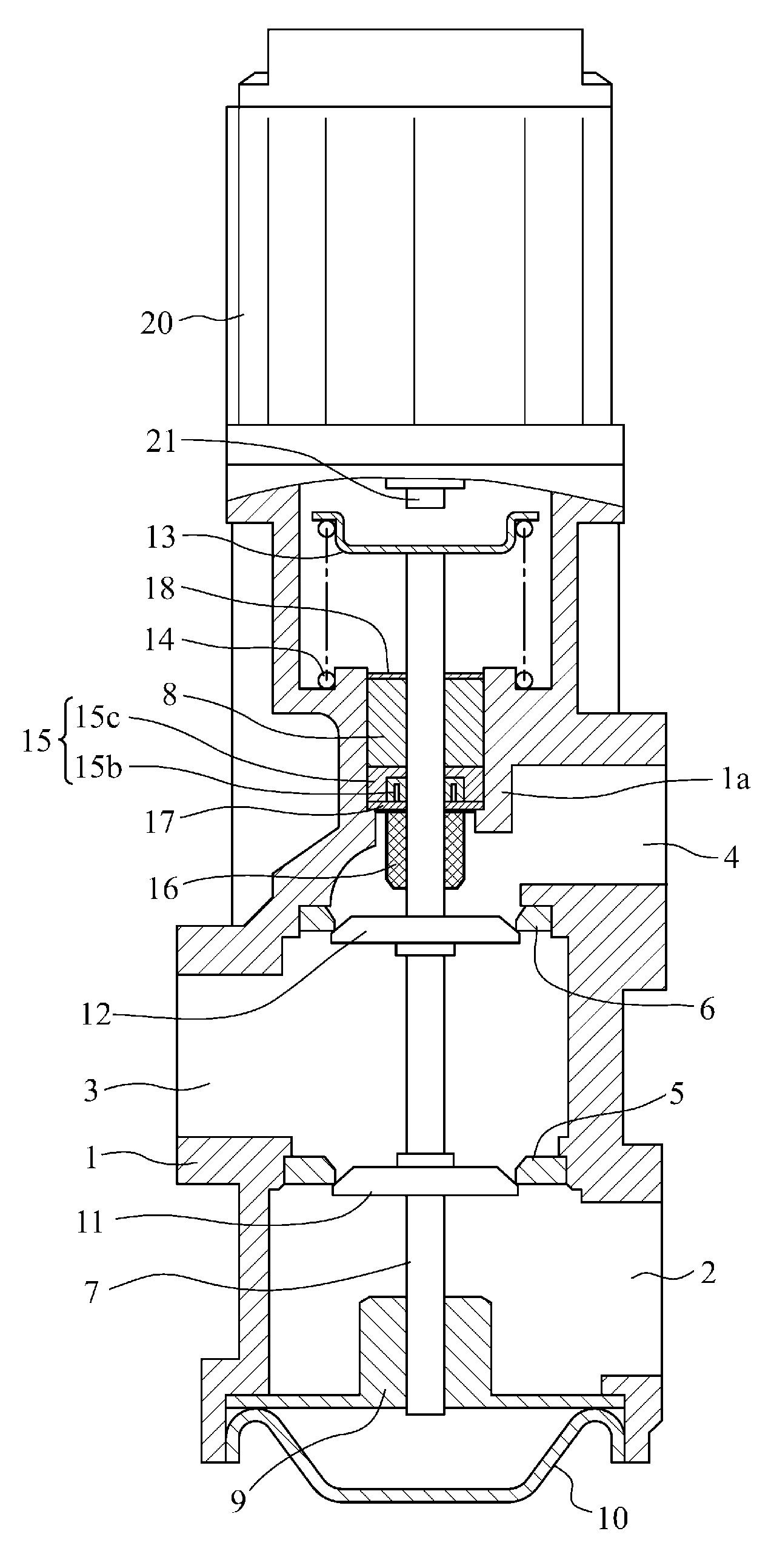
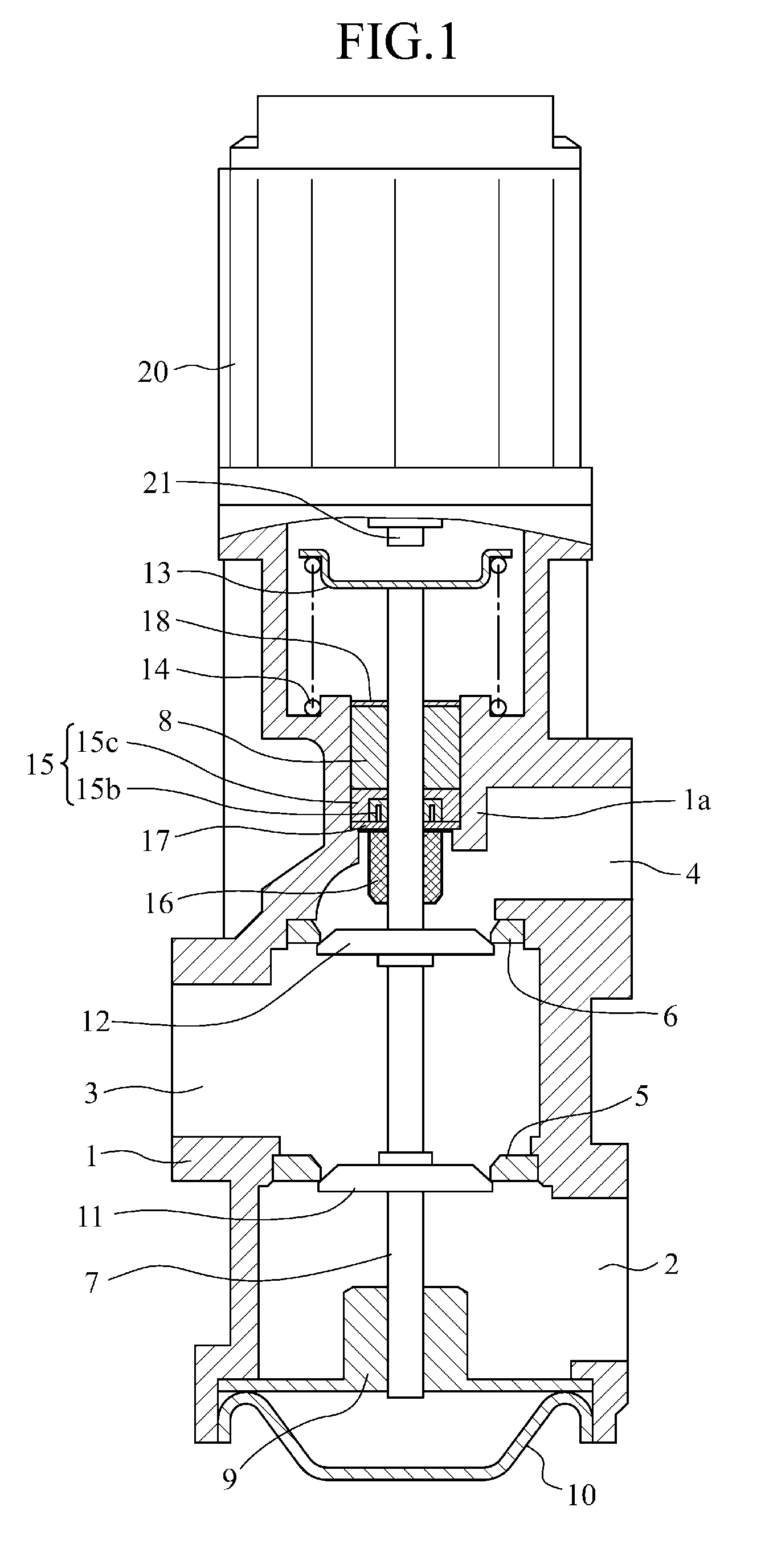
[0014]FIG. 1 is a longitudinal sectional front view, partly in section, showing an exhaust gas recirculation valve device in accordance with Embodiment 1 of the present invention, and FIG. 2 is a longitudinal sectional view of a sealing member. In FIGS. 1 and 2, a housing 1 is provided with a single exhaust gas inlet 3 and two exhaust gas outlets 2 and 4, and also has valve seals 5 and 6 which connect the exhaust gas inlet 3 and the two exhaust emission outlets 2 and 4 respectively.

[0015]A valve shaft 7 is supported in an internal central part of the housing 1 via a bearing 8 in such a way as be able to move in directions of the axis thereof. Furthermore, while a lower end of the valve shaft 7 is supported by a steady rest member 9 disposed at an end of the housing 1 in such a way as to be movable, and a lid 10 is disposed on an end surface of the housing 1 in such a way as to cover an outer surface of this steady rest member 9. This lid 10 bulges outwardly so as to ensure a range o...

embodiment 2

[0027]FIG. 5 is an enlarged vertical longitudinal sectional view showing a bearing and its surroundings in accordance with Embodiment 2 of the present invention. In this Embodiment 2, a sealing member 15 is formed integrally with a bearing 8. In this case, the bearing 8 has the function of a plug 15c. Because the sealing member 15 is thus formed integrally with the bearing 8, the component count is reduced and assembly of the components in a housing 1 is further improved.

[0028]In the embodiments illustrated in the figures, the case in which the sealing member 15 supported by the plug 15c is applied to the exhaust gas recirculation valve device disposed in the exhaust gas passage extending from an engine, for controlling the flow of the exhaust gas is explained. This sealing member 15 can be similarly applied to a valve device having another structure for controlling the flow of a gas.


PUM


Abstract

In an exhaust gas recirculation valve device, a sealing member 15 supported by a plug 15c is disposed between a portion of a housing 1 on an exhaust gas passage side of a bearing 8, and a valve shaft 7.

Description

FIELD OF THE INVENTION[0001]The present invention relates to an exhaust gas recirculation valve device that prevents an exhaust gas, a foreign object, water, and so on from leaking from a clearance gap between a valve shaft and a bearing to a sliding portion of the valve shaft and an actuator section for driving the valve shaft by disposing, for example, a sealing member in an exhaust gas passage.BACKGROUND OF THE INVENTION[0002]A conventional exhaust gas recirculation valve device has an exhaust gas passage which is formed in a housing thereof, and a valve disposed therein for opening and closing this exhaust gas passage. This valve is supported by a valve shaft and this valve shaft is supported by a bearing disposed in the housing. An actuator is attached to the housing, and an actuator shaft positioned along an extension of the axis of the valve shaft and a driving member for moving this actuator shaft forwardly and backwardly in directions of the axis of the valve shaft are buil...

Claims


Application Information

Patent Timeline
IPC IPC(8): F02M25/07
CPCF02M25/0789F02M25/0792Y02T10/121F16K1/44F16K41/04F02M25/0796F02M26/67F02M26/69F02M26/71
Inventor ZUI, TAKURONOJIMA, NAOSUKEWATANUKI, HARUOMIYOSHI, SOTSUO
Owner MITSUBISHI ELECTRIC CORP
Why Eureka
Try Eureka