Method and apparatus for recharging batteries in a more efficient manner

a battery charger and battery technology, applied in the field of more efficient battery chargers, can solve the problems of large amount of wasted energy, negative effect on the environment, and reduce the amount of power drawn by the battery charger, and achieve the effect of reducing the amount of power drawn

Inactive Publication Date: 2011-04-28
SUPERIOR COMM
View PDF27 Cites 40 Cited by
  • Summary
  • Abstract
  • Description
  • Claims
  • Application Information

AI Technical Summary

Benefits of technology

[0007]The power disablement condition can occur, for example, when the terminal is fully charged, the terminal is disconnected from the converter unit, and / or a charge time of the terminal exceeds the predetermined charge time threshold. This reduces an amount of power drawn by the battery charger when it would not be productive to be drawing power from the external power source. The converter unit can also periodically wake-up to monitor the terminal to determine whether the power disablement condition still exists. The power enablement condition can occur, for example, when the terminal is initially connected to the converter unit and / or the terminal needs to be charged. This allows the terminal to still be appropriately charged even when conserving energy.

Problems solved by technology

However, the conventional battery charger can draw power from the power source even when the electronic device is disconnected, or fully charged.
With the millions of power adapters in use today, this translates into a large amount of wasted energy and a negative effect on the environment.
This reduces an amount of power drawn by the battery charger when it would not be productive to be drawing power from the external power source.

Method used


Image

  • Method and apparatus for recharging batteries in a more efficient manner
  • Method and apparatus for recharging batteries in a more efficient manner
  • Method and apparatus for recharging batteries in a more efficient manner

Examples


Embodiment Construction

[0022]Apparatus, systems and methods that implement the embodiments of the various features of the present invention will now be described with reference to the drawings. The drawings and the associated descriptions are provided to illustrate some embodiments of the present invention and not to limit the scope of the present invention. Throughout the drawings, reference numbers are re-used to indicate correspondence between referenced elements.

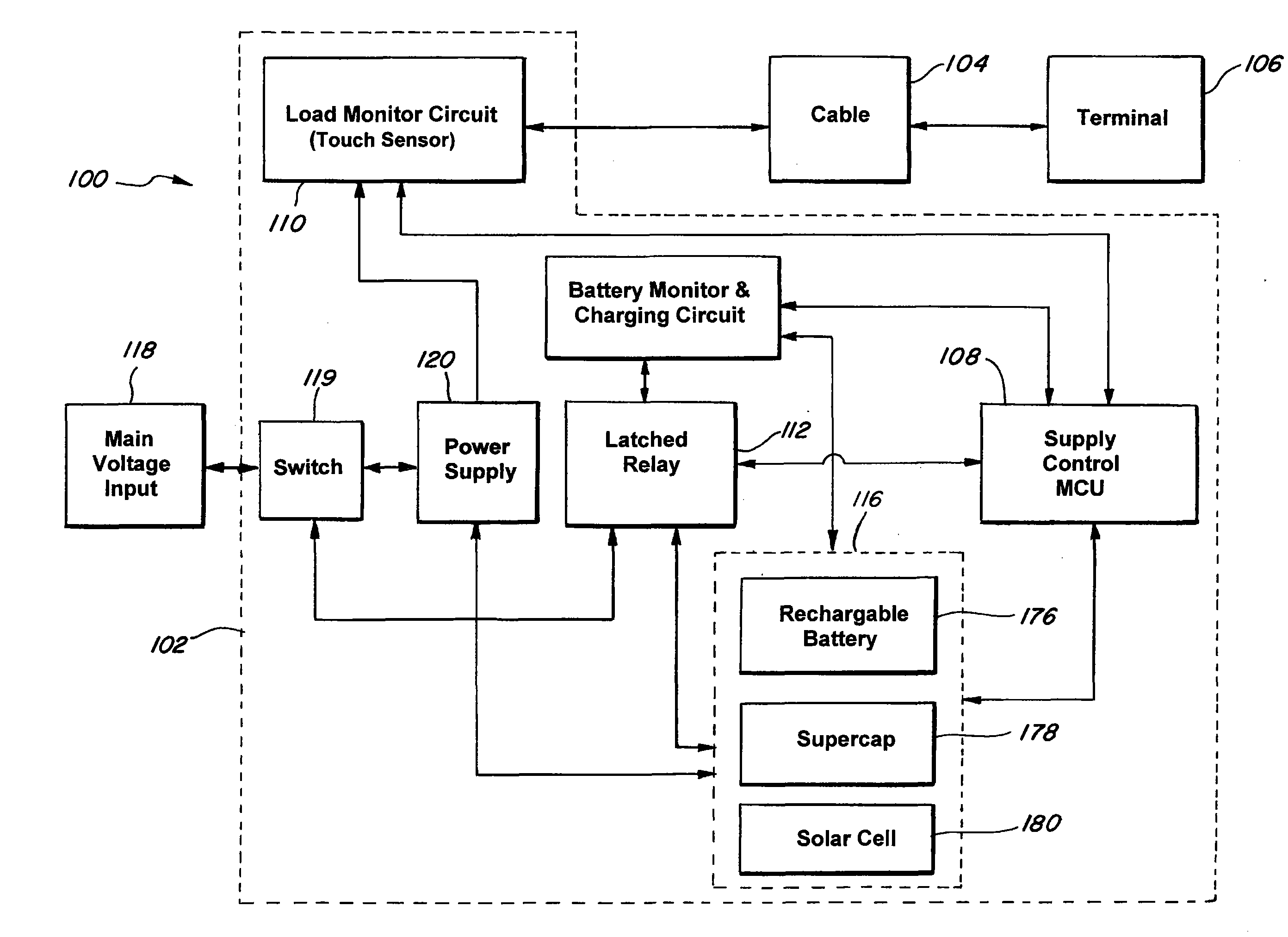
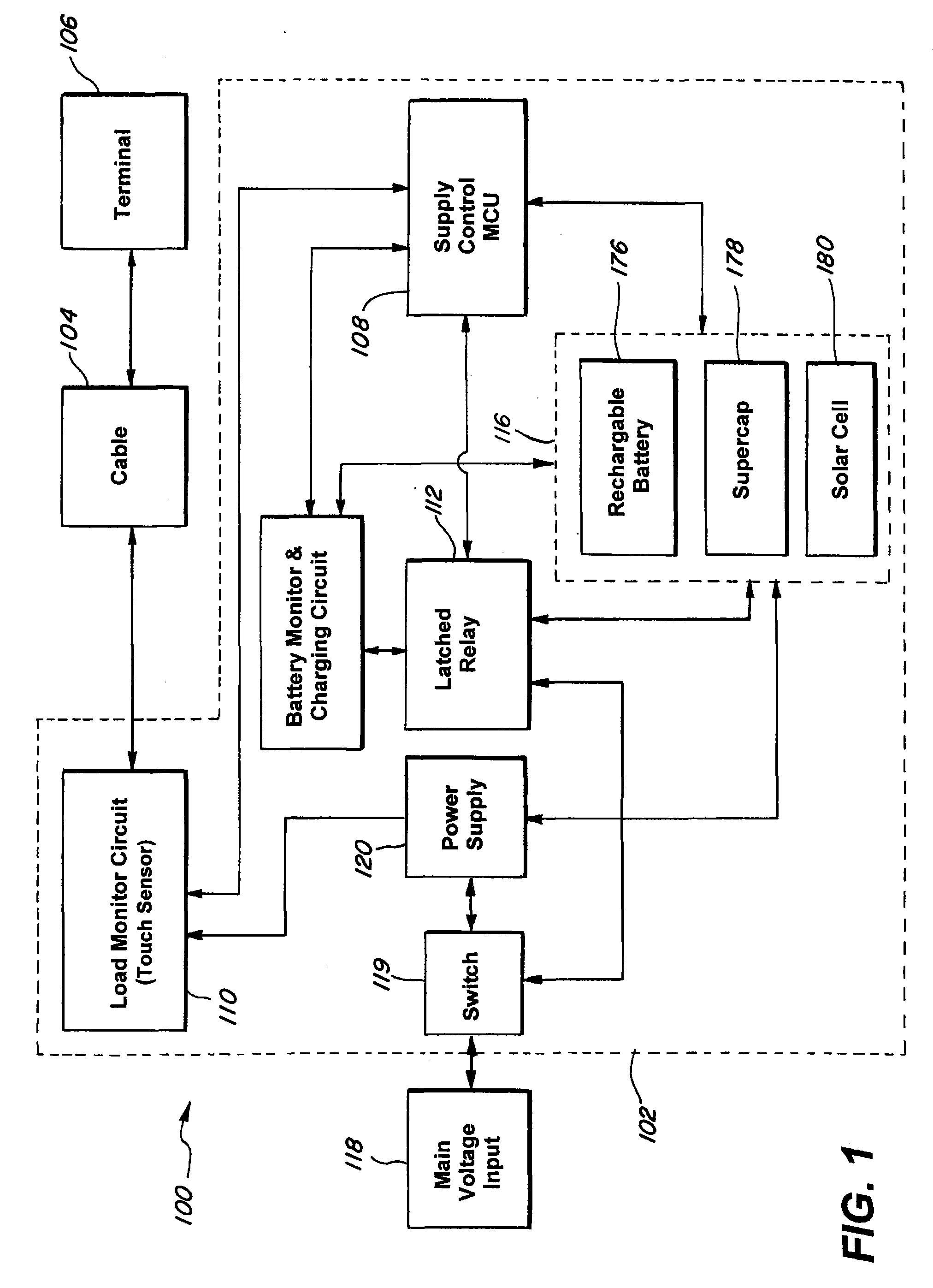
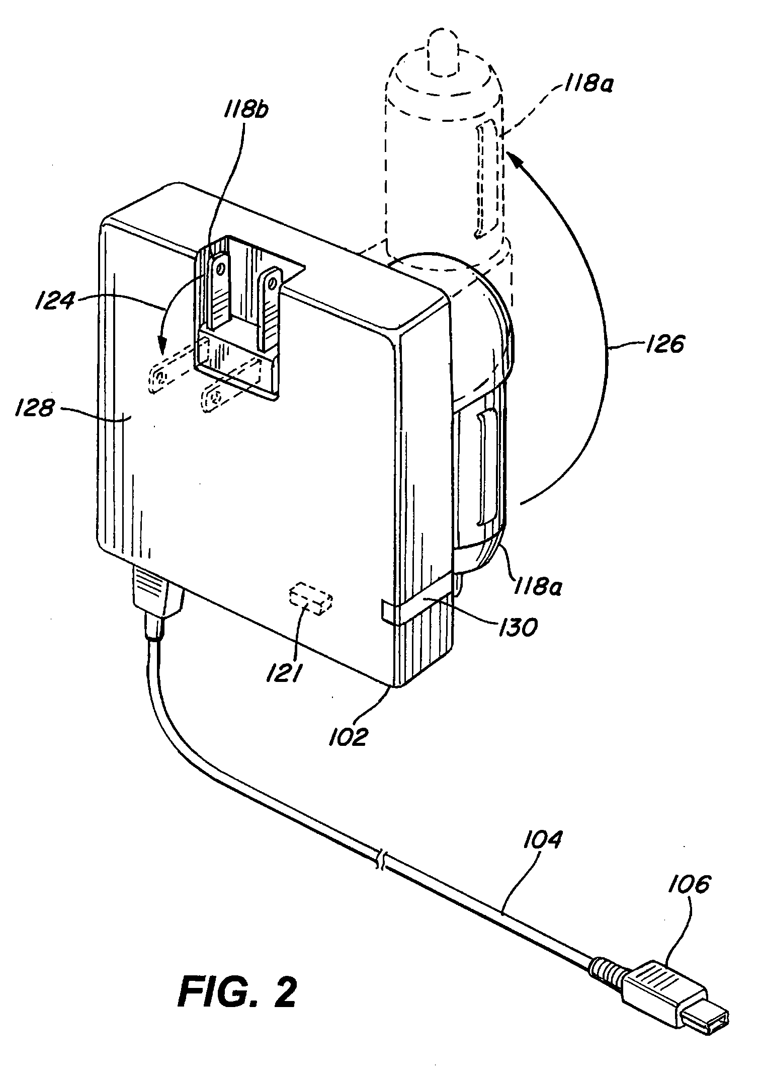
[0023]FIG. 1 is a block diagram of a battery charger 100, while FIG. 2 is a perspective view of the battery charger. The battery charger 100 includes, for example, a converter unit 102, a cable 104, a terminal 106, and / or a main voltage input 118.

[0024]The terminal 106 is connected to the cable 104 and can be an electronic device. The terminal 106 can be, for example, a music player, a cell phone, a laptop, a desktop computer, a personal digital assistant (PDA), a camera, or any other type of electronic device which includes a rechargeable bat...


PUM


Abstract

A battery charger including a converter unit, a terminal adaptor, a cable, a battery, and/or multiple power connectors. A terminal, such as an electronic device, can be connected to the converter unit using the cable or directly to the converter unit without the cable. The converter unit determines when to draw power from an external power and when to cease drawing power from the external power source by detecting a power enablement condition or a power disablement condition. The power disablement condition occurs when the terminal is fully charged, the terminal is disconnected from the converter unit, and/or a charge time of the terminal exceeds the predetermined charge time threshold. The power enablement condition occurs when the terminal is initially connected to the converter unit and/or the terminal needs to be charged. The battery supplies power to components of the converter unit and/or the terminal.

Description

BACKGROUND[0001]1. Field of the Invention[0002]The present invention relates to a method and apparatus for recharging batteries in a more efficient manner, and more specifically to a method and apparatus for optimizing the operational and down time of chargers or power supplies.[0003]2. Description of the Related Art[0004]A conventional battery charger has one end connected to a power source and another end connected to an electronic device. The conventional battery charger draws power from the power source to supply to the electronic device. However, the conventional battery charger can draw power from the power source even when the electronic device is disconnected, or fully charged. In some situations, the excess consumption can be, for example, 15 mW or more. With the millions of power adapters in use today, this translates into a large amount of wasted energy and a negative effect on the environment.[0005]Thus, there is a need for a method and apparatus for optimizing the opera...

Claims


Application Information

Patent Timeline
Patent Type & Authority Applications(United States)
IPC IPC(8): H02J7/04H02J7/00
CPCH02J7/0036H02J7/0052H02J2007/0049H02J7/0055H02J7/0049H02J2207/40H02J2207/20H02J7/0042H02J7/02H02J7/345H02J7/35H02J9/007H02J7/00
Inventor CHEN, GEORGEMKHITARIAN, HARRYSENTOSA, SAMUELSU, DAVID P.
Owner SUPERIOR COMM
Why Eureka
Try Eureka