
System and method for determination of a horizontal minimum of digital values

a technology of digital values and system methods, applied in the field of microprocessor instructions, can solve the problems of reducing overall processing efficiency, increasing cost, and occupying a large amount of spa

Active Publication Date: 2011-04-28
VIA TECH INC
View PDF5 Cites 3 Cited by
  • Summary
  • Abstract
  • Description
  • Claims
  • Application Information

AI Technical Summary

Benefits of technology

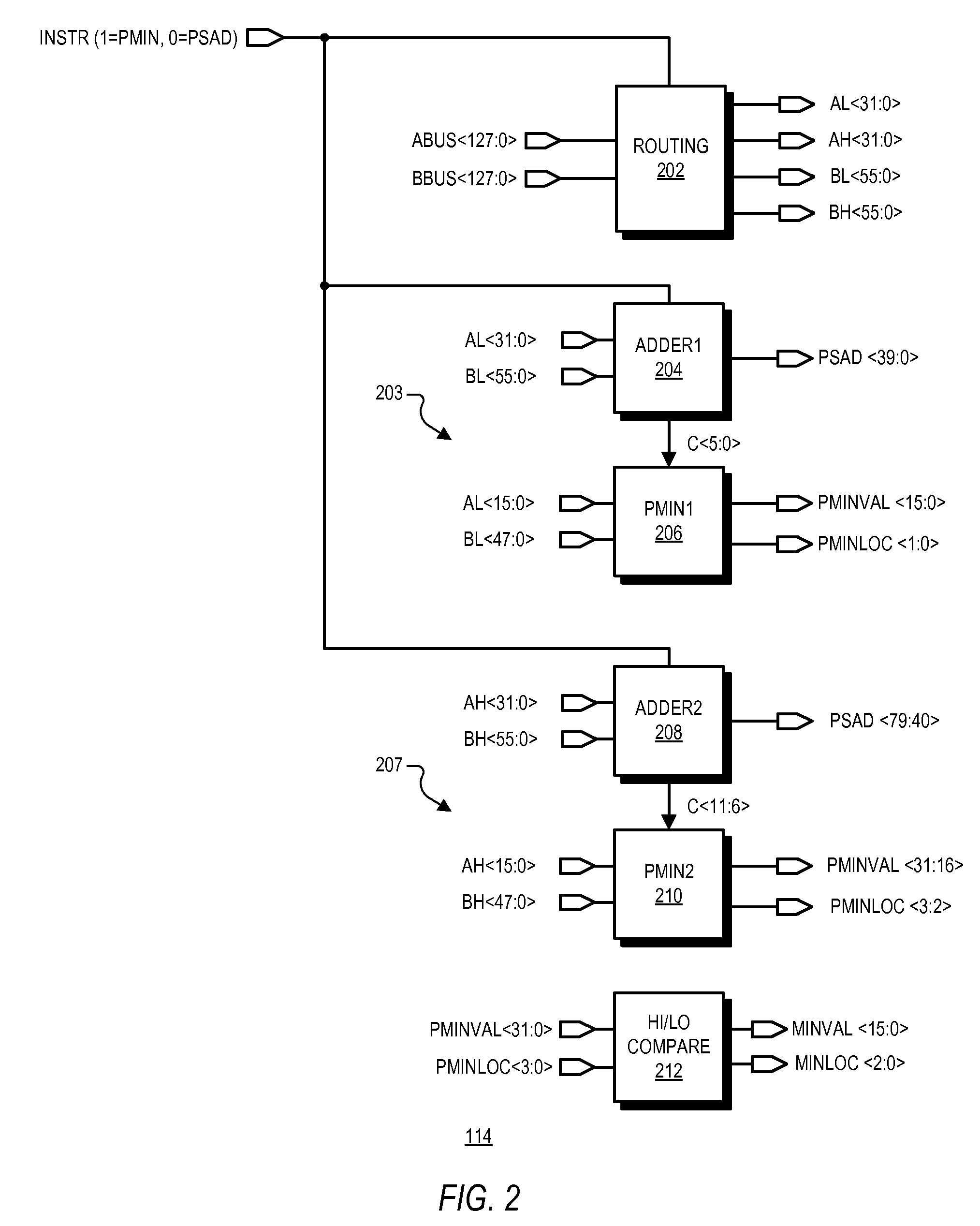
[0009]Each propagate output indicates whether a carry input would be propagated through an upper adder of a corresponding difference circuit. The compare circuit may be configured to decode comparison bits to provide minimum bits in which each minimum bit identifies whether a corresponding digital value is a lesser value. A location circuit may be provided to identify a location of the minimum digital value in a memory. The system may be integrated on a microprocessor chip for performing a fast horizontal minimum instruction.

Problems solved by technology

Each 16-bit comparator, however, consumes a significant amount of space on the microprocessor die thereby increasing cost and reducing overall processing efficiency.

Method used


Image

  • System and method for determination of a horizontal minimum of digital values
  • System and method for determination of a horizontal minimum of digital values
  • System and method for determination of a horizontal minimum of digital values

Examples


Embodiment Construction

iment;

[0014]FIG. 3 is a schematic diagram of the routing circuit of FIG. 2 according to an exemplary embodiment;

[0015]FIG. 4 is a schematic and block diagram of the ADDER1 circuit of FIG. 2 according to an exemplary embodiment;

[0016]FIG. 5 is a block and schematic diagram of the first difference circuit of FIG. 4 according to an exemplary embodiment;

[0017]FIG. 6 is a block diagram of the first sum circuit of FIG. 4 according to an exemplary embodiment;

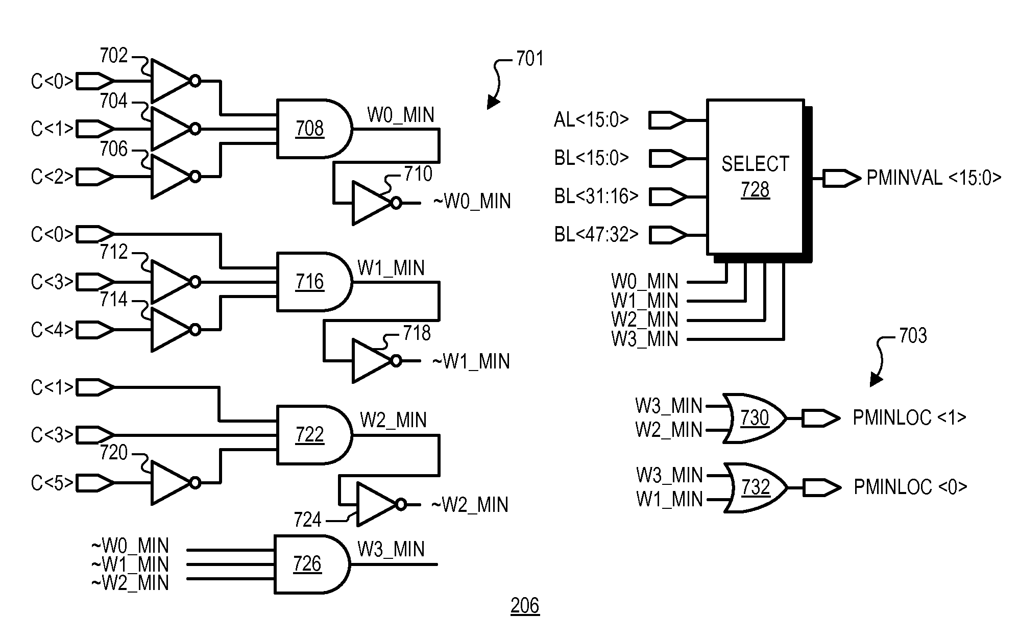
[0018]FIG. 7 is a schematic and block diagram of the PMIN1 circuit of FIG. 2 according to an exemplary embodiment; and

[0019]FIG. 8 is a schematic and block diagram of the HI / LO comparator circuit of FIG. 2 according to an exemplary embodiment.

DETAILED DESCRIPTION

[0020]The following description is presented to enable one of ordinary skill in the art to make and use the present invention as provided within the context of a particular application and its requirements. Various modifications to the preferred embodiment will, however, be app...


PUM


Abstract

A system for fast determination of a horizontal minimum of multiple digital values including a difference circuit and a compare circuit. The difference circuit may include first and second adders in which the first adder compares upper bits of a first digital value with upper bits of a second digital value and provides a first carry output and a propagate output. The second adder compares lower bits of the first digital value with lower bits of the second digital value and provides a second carry output. The compare circuit determines whether the first digital value is greater than the second digital value based on the carry and propagate outputs. Multiple difference circuits may be used to compare each of multiple digital values with every other digital value to provide corresponding compare bits, which are then used to determine a minimum one of the digital values and its corresponding location.

Description

CROSS-REFERENCE TO RELATED APPLICATIONS[0001]This application is related to co-pending U.S. patent application Ser. No. ______ (Docket: CNTR.2458), filed concurrently herewith entitled SYSTEM AND METHOD OF USING COMMON ADDER CIRCUITRY FOR BOTH A HORIZONTAL MINIMUM INSTRUCTION AND A SUM OF ABSOLUTE DIFFERENCES INSTRUCTION, which has a common assignee and which has common inventors.BACKGROUND OF THE INVENTION[0002]1. Field of the Invention[0003]The present invention relates to microprocessor instructions, and more particularly, to a system and method for determination of the minimum one of a set of digital values, otherwise referred to as a horizontal minimum.[0004]2. Description of the Related Art[0005]Modern day microprocessors are often configured to perform media instructions to improve the efficiency of multimedia applications and the like. For example, one or more media instructions may be included in the microprocessor architecture to identify a horizontal minimum, which is the...

Claims


Application Information

Patent Timeline
Patent Type & Authority Applications(United States)
IPC IPC(8): G11C8/10H03K19/20
CPCG06F7/02
Inventor STORTZ, ROCHELLE L.BERTRAM, RAYMOND A.
Owner VIA TECH INC
Learn More