
Multiband Mobile Communication Device and Antenna Thereof

Active Publication Date: 2011-04-28
ACER INC
View PDF2 Cites 38 Cited by
  • Summary
  • Abstract
  • Description
  • Claims
  • Application Information

AI Technical Summary

Benefits of technology

According to one preferred embodiment of the pres

Problems solved by technology

As a result, even a communication device having a conventional coupled-fed antenna cannot cover all required operating bands.
Hence, the abovementioned conventional coupling-feed mechanism cannot provide a mobile communication device to completely cover 8-band LTE / GSM / UMTS operations, including 3-band LTE700 / GSM850 / 900 (698˜960 MHz) operations and 5-band GSM1800 / 1900 / UMTS / LTE2300 / 2500 (1710˜2690 MHz) operations, while still keeping the antenna with a small size.

Method used


Image

  • Multiband Mobile Communication Device and Antenna Thereof
  • Multiband Mobile Communication Device and Antenna Thereof
  • Multiband Mobile Communication Device and Antenna Thereof

Examples


Embodiment Construction

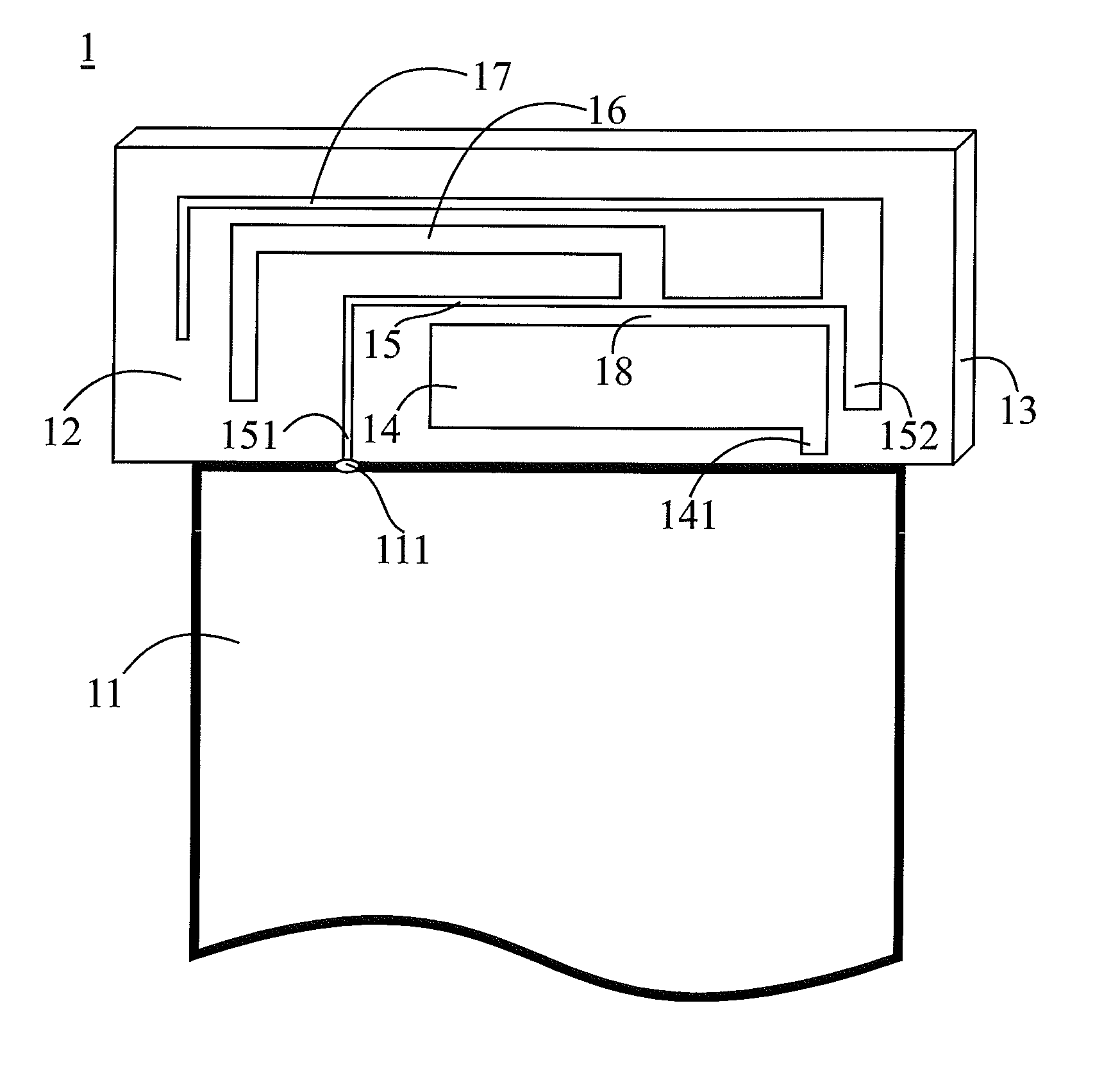
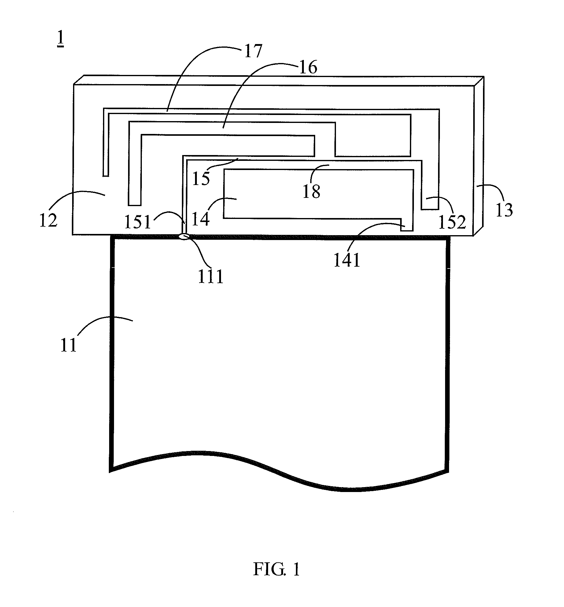
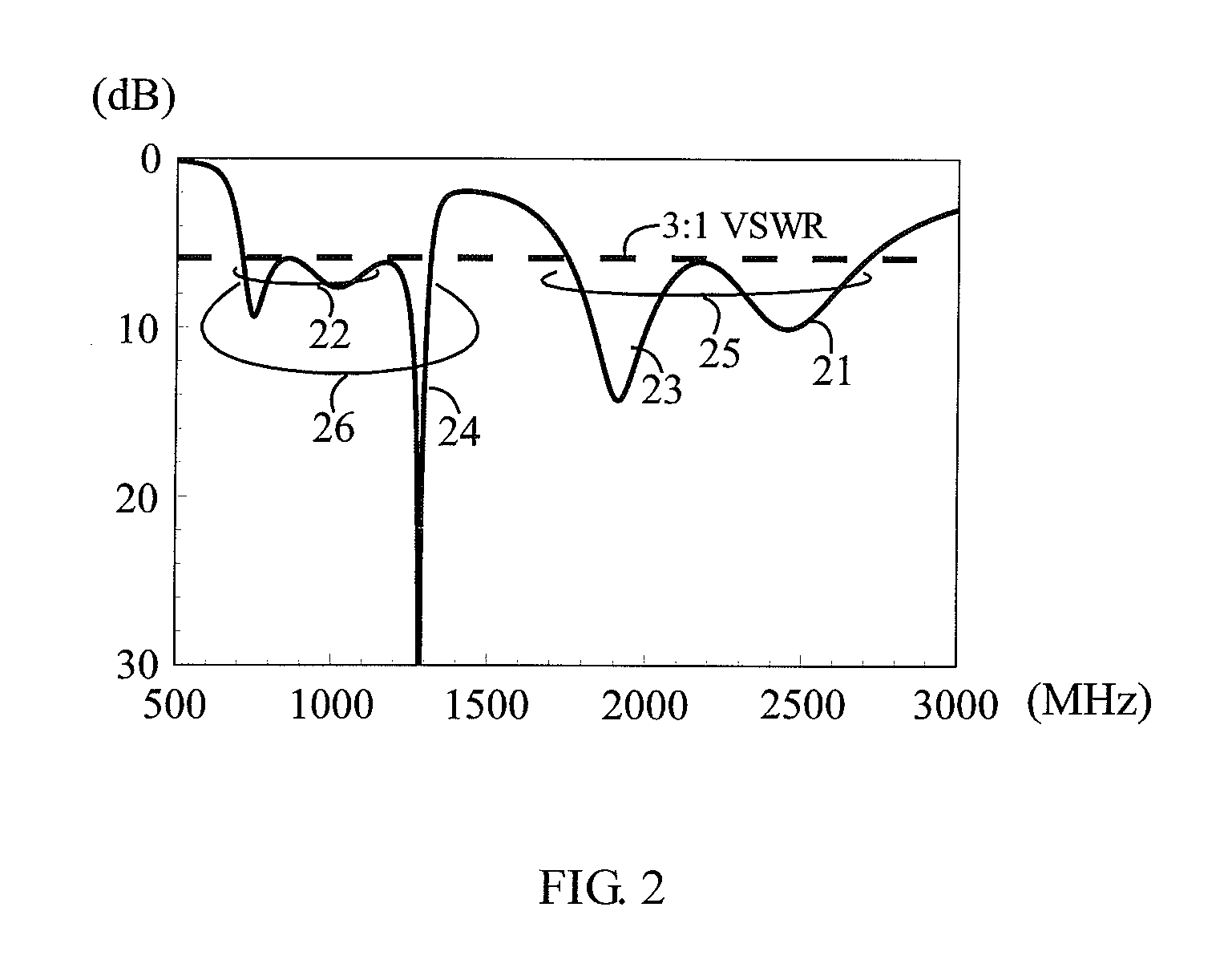
Please refer to both FIG. 1 and FIG. 2. FIG. 1 illustrates a structural view of a multiband mobile communication device in a first embodiment of the present invention. FIG. 2 illustrates a diagram of a simulated return loss of the mobile communication device in the first embodiment of the present invention. The multiband mobile communication device 1 has a ground plane 11 and an antenna 12. The ground plane 11 is a system ground plane of a mobile communication device, or a system ground plane of a mobile phone. The antenna 12 can be formed on a dielectric substrate 13 by means of printing, etching or injection-molding. The antenna 12 comprises: a monopole 14, a shorted radiating portion 15, a first radiating branch 16, and a second radiating branch 17.

A feeding end 141 of the monopole 14 is a feeding point of the antenna 12. The monopole 14 generates a first (also the highest) resonant mode 21 (as shown in FIG. 2) of the antenna 12. In this embodiment, the monopole 14 is approximate...


PUM


Abstract

The present invention is related to a multiband mobile communication device. The mobile communication device has a ground plane and an antenna. The antenna is disposed on a dielectric substrate. The antenna comprises a monopole, a shorted radiating portion, a first radiating branch, and a second radiating branch. The monopole comprises a feeding end, and the feeding end is the feeding point of the antenna. The shorted radiating portion has a shorting end electrically connected to the ground plane, and its other end is left open. The shorted radiating portion is extended along the monopole and has a coupling gap to the monopole. The first radiating branch has an end electrically connected to the shorted radiating portion, and its other end is left open. The first radiating branch is extended toward the shorting end of the shorted radiating portion and located on the opposite side of the monopole. The second radiating branch has an end electrically connected to the shorted radiating portion, and its other end is left open. The second radiating branch is extended along the first radiating branch, with the first radiating branch located between the second radiating branch and the shorted radiating portion.

Description

BACKGROUND OF THE INVENTION1. Field of the InventionThe present invention relates to a mobile communication device and antenna thereof; more particularly, the present invention relates to a mobile communication device and antenna thereof capable of performing multiband operations.2. Description of the Related ArtThe development of mobile communication devices is getting faster. With the vigorous development of the wireless wide area network (WWAN) and long term evolution (LTE) techniques, people have higher and higher expectations of mobile communication devices. Because each country adopts different types of communication systems, there are numerous wireless network systems in the market, such as LTE700 / 2300 / 2500, GSM850 / 900 / 1800 / 1900 and UMTS. Therefore, a mobile communication device needs not only to be light, thin and compact, but also to cover multiband operations. In order to meet the requirement of multiband operations, a mobile communication device can be designed to utilize...

Claims


Application Information

Patent Timeline
IPC IPC(8): H01Q1/24H01Q5/10
CPCH01Q1/243H01Q5/392H01Q9/40H01Q1/38
Inventor WONG, KIN-LUCHEN, WEI-YU
Owner ACER INC
Features
  • Generate Ideas
  • Intellectual Property
  • Life Sciences
  • Materials
  • Tech Scout
  • Unparalleled Data Quality
  • Higher Quality Content
  • 60% Fewer Hallucinations
Learn More