Flat-plate antenna and electric apparatus with the same

a flat-plate antenna and electric apparatus technology, applied in the field of compact and thin flat-plate antennas, can solve the problems of antenna failure, labor-intensive and time-consuming, and increase the cost of manufacturing and a development period

Inactive Publication Date: 2003-07-29
HITACHI CABLE
View PDF9 Cites 58 Cited by
  • Summary
  • Abstract
  • Description
  • Claims
  • Application Information

AI Technical Summary

Problems solved by technology

The above problems are attributable to the fact that when it is intended to encase a dedicated antenna in the housing or casing (hereinafter, abbreviated as housing in general) of a portable terminal or an electric appliance, a dedicated space must be preserved inside the housing.
This leads to an increase in the cost of manufacturing and an extension of a development period.
However, in this method, when the portable terminal or electric appliance is moved, the external antenna must be often dismounted.
This is labor-intensive and time-consuming.
At worst, the antenna may fail while the cable or the like are led to and fro or because of an unexpected trouble.
Besides, the installed position of the portable terminal or electric appliance cannot be selected freely.
This is discouraging to a user.
Moreover, when the flat-plate antenna is housed in a portable terminal or each of home electric appliances that are interconnected over a wireless network at home, even if the portable terminal or home electric appliance must be moved, it is unnecessary to dismount, remount or readjust an external antenna.

Method used


Image

  • Flat-plate antenna and electric apparatus with the same
  • Flat-plate antenna and electric apparatus with the same
  • Flat-plate antenna and electric apparatus with the same

Examples


second example

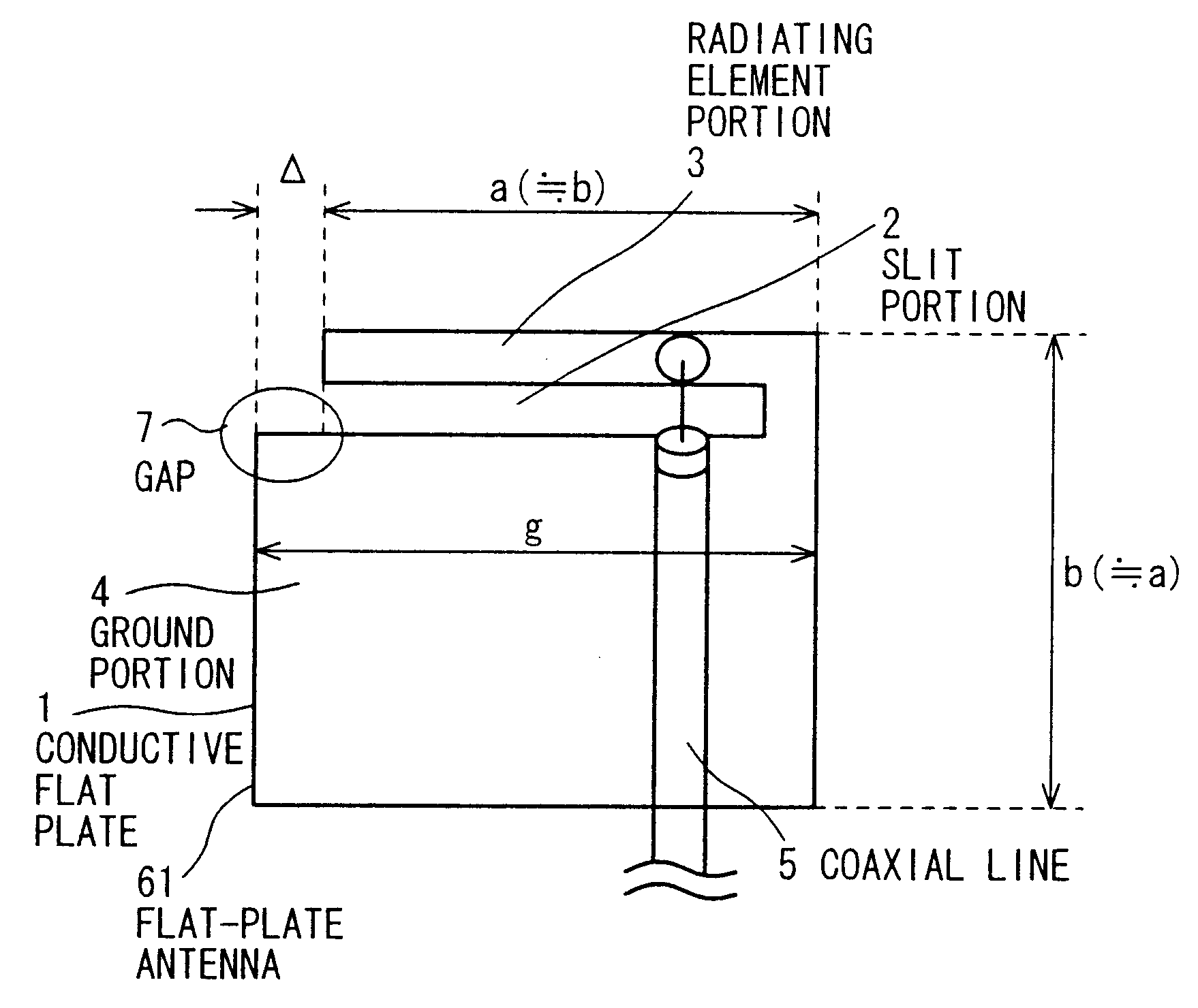
A second example of the present invention will be described in reference to FIGS. 9 and 10. FIG. 9 shows an example realized by fixing the width of the gap 7 of the first example to a certain value and changing the length b of the conductive flat plate 1 thereof. In this case, the standing-wave ratio of one separate monopole antenna varies with the change in the length b of the conductive flat plate 1. The separate monopole antenna is electrically formed in a direction substantially perpendicular to the length direction of the radiating element portion 3, and passes through the conductive portion linking the radiating element portion 3 and ground portion 4. The electromagnetic field that is induced in the slit portion 2 and has the direction thereof changed with the inclusion of the gap 7 further changes its direction with the variation of the standing-wave ratio. Consequently, as shown in FIG. 10, the antenna exhibits directivity in the direction of the gap 7 in the same manner as ...

third example

A third example of the present invention will be described in reference to FIGS. 11 and 12. FIG. 11 shows the appearance of a typical notebook-size personal computer 8 (hereinafter, abbreviated as notebook computer) having two flat-plate antennas 61 located above a liquid crystal display (LCD) thereof. The flat-plate antennas 61 are identical to the flat-plate antenna 61 of the first and second example except that the length b of the conductive flat plate 1 is larger. Referring to FIG. 11, the flat-plate antennas 61 are placed in a space created between the back of the LCD 9 of the notebook computer 8 and the wall of the housing of the notebook computer 8 in such a manner as described below. Namely, the radiating element portion 3 of each flat-plate antenna 61 is exposed above the LCD 9. The majority of the ground portion 4 is hidden behind the LCD 9. At this time, the flat-plate antennas 61 are fixed to the housing of the notebook computer 8 using an adhesive tape such as a celloph...

fourth example

A fourth example of the present invention will be described in reference to FIGS. 13 and 14. FIG. 13 shows the appearance of a notebook computer having the flat-plate antennas 61 of the third example of the present invention housed therein. The flat-plate antennas 61 according to the present invention exhibit directivities in specified directions like the flat-plate antennas of the first and second examples. Thus, exhibition of directivities in directions other than the specified directions is suppressed. Even when the plurality of flat-plate antennas 61 according to the present invention is placed adjacently to each other, electromagnetic interference occurring between adjoining antennas is suppressed. The flat-plate antennas 61 can therefore be placed adjacently to each other with a smaller distance between them than ordinary antennas are. Consequently, the flat-plate antennas 61 can be placed in such a limited space as shown in FIG. 13.

FIG. 14 shows the measures of directivities ...


PUM


Abstract

Provided are a low-cost and high-performance antenna that can be placed in a small space inside a portable terminal or an electric appliance or housed in a wall or the like, and an electric apparatus having the antenna. A slit having a specified width and a specified length is formed in a conductive flat plate having a specified width and a specified length. A radiating element portion shaped like a monopole antenna and a ground portion (having a specified width) are formed with the slit between them. The width of the conductive flat plate (the length of the radiating element portion) is substantially a multiple of a quarter of a wavelength attained at the operating frequency of the antenna by an odd-numbered value.

Description

1. Field of the InventionThe present invention relates to a compact and thin flat-plate antenna that is formed with a conductive flat plate, and readily housed in an electric apparatus such as a portable terminal or an electric appliance or in a wall or the like.2. Prior ArtIn recent years, various kinds of antennas dedicated to portable telephones or mobile computers (hereinafter, abbreviated as portable terminal in general) have become more and more compact except large-scale antennas for use at base stations or in satellite broadcasting. The antenna dedicated to the portable terminal is requested to be especially compact. Along with the tendency of the portable terminal toward a compact design, the antenna dedicated to the portable terminal is demanded to clear the problem of an installed space and to satisfy the demand for high performance despite limitations to the volume of the antenna. Moreover, when a wireless network is constructed at home as discussed in earnest recently, ...

Claims


Application Information

Patent Timeline
Patent Type & Authority Patents(United States)
IPC IPC(8): H01Q13/10H01Q1/22H01Q1/38H01Q9/04G06F1/16H01Q9/30
CPCG06F1/1616G06F1/1698H01Q1/22H01Q1/2266H01Q1/38H01Q9/0421H01Q13/10
Inventor IKEGAYA, MORIHIKOSUGIYAMA, TAKAHIROTATE, HISASHI
Owner HITACHI CABLE
Why Eureka
Try Eureka