
Tension regulator applied to a timing belt

a technology of a timing belt and a tension regulator, applied in the direction of belt/chain/gearring, mechanical equipment, belts, etc., can solve the problems of easy damage to the stability support, unsafe driving, etc., and achieve the effect of promoting driving safety and stable operation

Inactive Publication Date: 2011-04-28
GONG SHUN TECH
View PDF0 Cites 3 Cited by
  • Summary
  • Abstract
  • Description
  • Claims
  • Application Information

AI Technical Summary

Benefits of technology

[0011]The object of the present invention is to provide a tension regulator applied to a timing belt, which provides a firm support for a propelling member to avoid an over-protruding incident and preferably prevents hydraulic oil from leaking out in view of any undue pressure; whereby, a stable operation of the present invention could be achieved to promote the driving safety.
[0012]The tension regulator applied to a timing belt in accordance with the present invention comprises a body, an elastic device disposed in the body, a propelling device elongated into the body as well as propelled by the elastic device, and a blocking device sealing the body as well as blocking the propelling device. Wherein, a first blocking member is fixed between a plunger of the propelling device and the blocking device for giving a synchronous support, thereby permitting a smooth sliding movement of the propelling device while the plunger drives the propelling member to displace. Furthermore, the arrangement of the blocking member substantially leads to air unable to penetrate into the body during the sliding of the plunger, and the hydraulic oil flowing along with the sliding plunger would not scatter to impact the blocking member. As a result, the hydraulic oil would not readily leak out. In addition, since the first blocking member could reinforce the limitation to the sliding movement of the plunger, the propelling member could be accordingly prevented from an over-protruding incident. Thence, the tension regulator preferably facilitates a stable operation and efficiently promotes a driving safety.
[0014]wherein, a first blocking member being disposed between a plunger and the blocking device as well as engaged with the sliding space; a sliding movement of the propelling member brought about by the plunger would not affect the first blocking member, so that a stable support would be provided to prop up the sliding movement of the propelling member and the hydraulic oil would be prevented from scattering in time of the plunger being moved.

Problems solved by technology

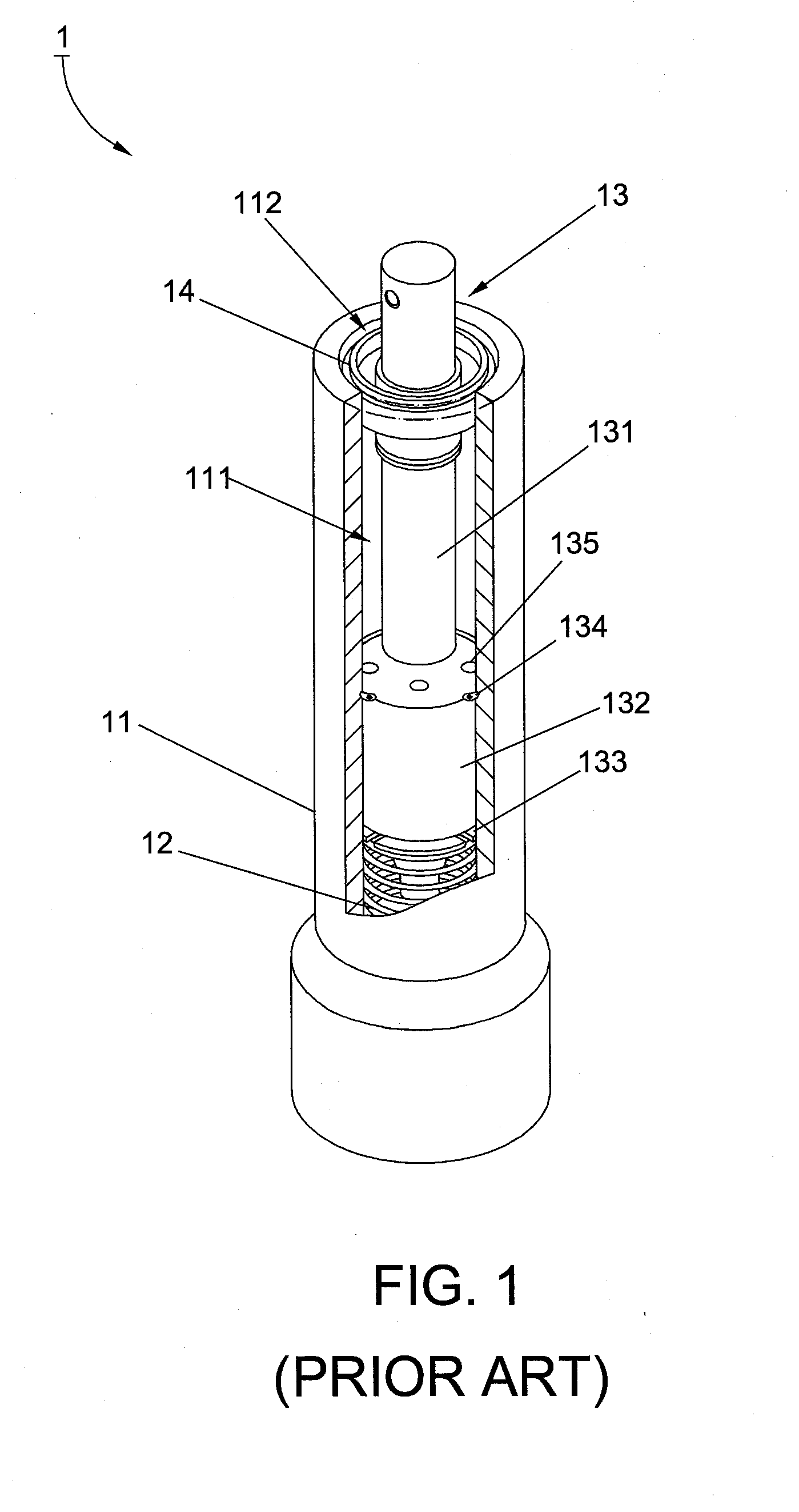
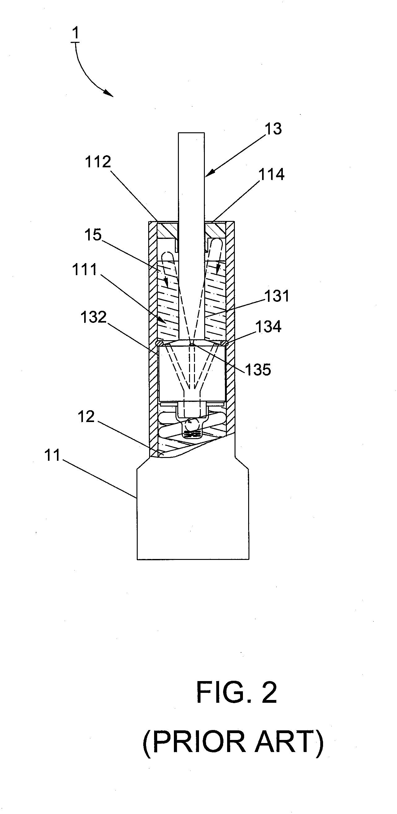
1. When the replenishment of the hydraulic oil 15 to the conventional tension regulator 1 is artificially sealed with the blocking device 14, air in the sliding space 111 could not be entirely exhausted; namely, the air still exists in the body 11. As a result, while the plunger 132 slides in the sliding space 111, the air would mingle with the flowed hydraulic oil 15, which incurs the air to pervade the sliding space 111. Whereby, since the air is contractible, an incomplete operation of the tension regulator would be unfavorably resulted, thereby adversely incurring an unsafe driving.
However, since the blocking device 14 is made of rubber, which has a softer characteristic, an unstable support is easily caused in time of stretching or contracting the propelling member 131.

Method used


Image

  • Tension regulator applied to a timing belt
  • Tension regulator applied to a timing belt
  • Tension regulator applied to a timing belt

Examples


Embodiment Construction

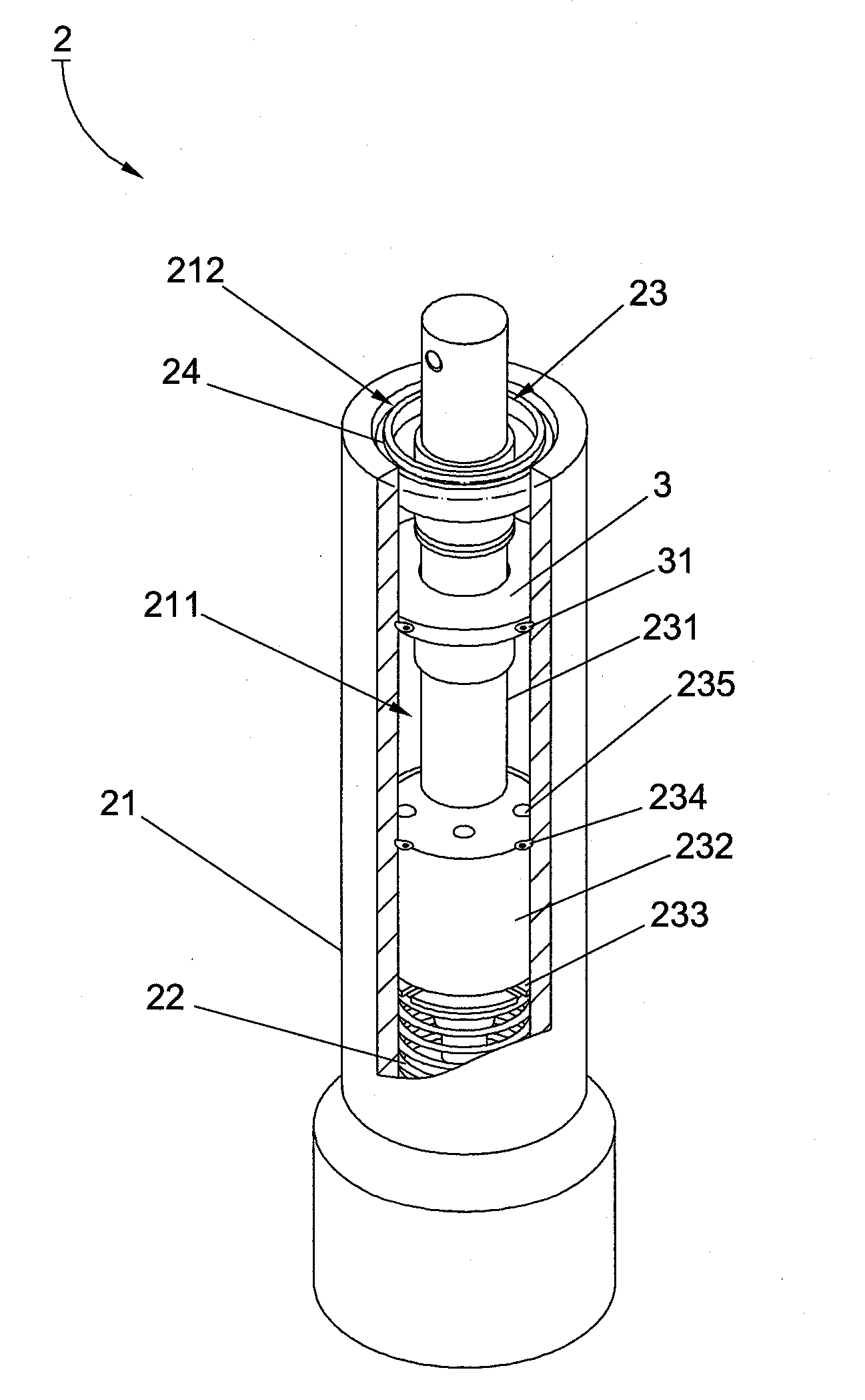
[0027]FIG. 3 shows a first preferred embodiment of the present invention, a tension regulator 2 adapted for a timing belt comprising a body 21, an elastic device 22 disposed in the body 21, a propelling device 23 disposed in the body 21 as well as propelled by the elastic device 22, and a blocking device 24 sealing the body 21 and blocking the propelling device 23. Wherein, a sliding space 211 is formed inside the body 21 for being filled with hydraulic oil 25 (shown in FIG. 4). Concurrently, an opening 212 is defined on the body 21 for the sliding space 211 to communicate with the exterior thereby. The propelling device 23 includes a propelling member 231 elongated into the sliding space 211 as well as protruded out of the blocking device 24, a plunger 232 disposed on the propelling member 231 for sliding inside the sliding space, a controlling member 233 disposed on the plunger 232, and a limiting member 234 disposed on the sliding space 211 for limiting a sliding movement of the ...


PUM


Abstract

A tension regulator employs a first blocking member fixed between a plunger on a propelling member and the blocking device to permit a smooth sliding movement of the propelling member to be achieved via a stable support while the plunger driving the propelling member of the propelling device. Additionally, the reinforced limitation to the sliding movement of the plunger provided by the first blocking member could accordingly prevent the propelling member from an over-protruding incident. Thence, since hydraulic oil is properly blocked by the first blocking member, no leakage of the oil would adversely occur, and no air would unfavorably enter into the sliding space in time of the sliding. Thence, the tension regulator possesses a more stable operation, and a driving safety could be promoted.

Description

BACKGROUND OF THE INVENTION[0001]1. Field of the Invention[0002]The present invention relates to a tension regulator, particularly to a tension regulator applied to a timing belt.[0003]2. Description of the Related Art[0004]Referring to FIGS. 1 and 2, a conventional tension regulator 1 applied to a timing belt comprises a body 11, an elastic device 12 disposed in the body 11, a propelling device 13 elongated into the body 11 for being propelled by the elastic device 12, and a blocking device 14 sealing the body 11 as well as blocking the propelling device 13. Wherein, the body 11 has a sliding space 111, whose diameter is uniform and whose interior is capable of filling with hydraulic oil 15, and an opening 112 formed on the body 11 for the sliding space 111 to communicate with an exterior through the opening 112. Moreover, the propelling device 13 has a propelling member 131 elongated into the sliding space 111 as well as protruded out of the blocking device 14, a plunger 132 dispo...

Claims


Application Information

Patent Timeline
Patent Type & Authority Applications(United States)
IPC IPC(8): F16H7/08
CPCF16H7/0836F16H2007/0893F16H2007/0859F16H2007/0806
Inventor WANG, GUAN-REN
Owner GONG SHUN TECH
Learn More