Foldable Attachment Clip

a clip and folding technology, applied in the field of folding clips, can solve the problems of user movement restriction, clip cannot bend in the assembled condition, and the “j” hook tends to be disengaged

Active Publication Date: 2011-05-05
ILLINOIS TOOL WORKS INC
View PDF19 Cites 13 Cited by
  • Summary
  • Abstract
  • Description
  • Claims
  • Application Information

AI Technical Summary

Benefits of technology

[0007]The present invention offers advantages and alternatives over the prior art by providing a foldable attachment clip assembly including a receiving body portion having a hollow interior and a slotted opening extending along the length which receives and retains a crossbar of a stirrup connection portion. The crossbar of the stirrup connection portion is adapted for press-fit insertion through the relatively narrow width slotted openi

Problems solved by technology

While such prior structures are suitable for many applications, one deficiency is that the clip cannot bend in the assembled condition.
Thus, a user's movement may be restricted.
Moreover, i

Method used


Image

  • Foldable Attachment Clip
  • Foldable Attachment Clip
  • Foldable Attachment Clip

Examples


Embodiment Construction

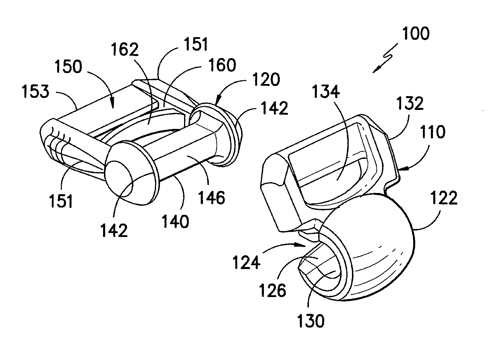
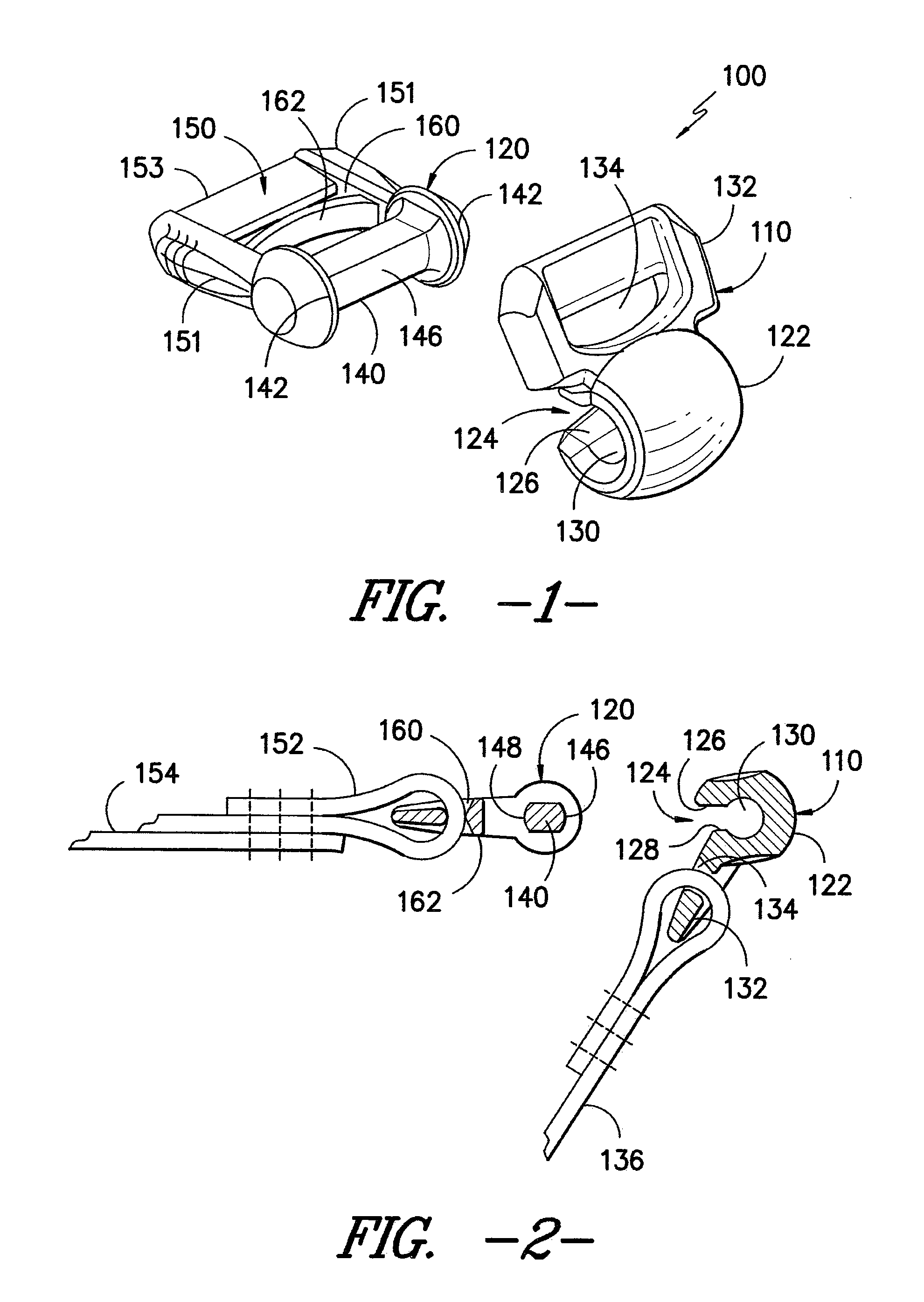
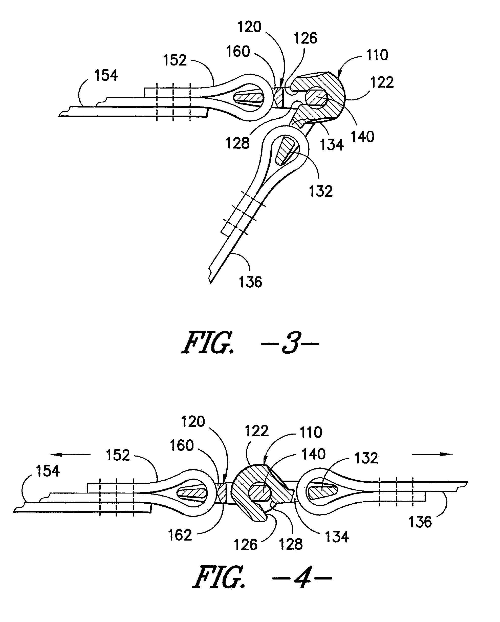
[0025]Exemplary embodiments of the invention will now be described in reference to the drawings, wherein like reference numerals designate like elements in the various views. Referring now in particular to FIGS. 1-4, a clip assembly 100 is illustrated. As shown, the clip assembly 100 includes a hook member 110 and a cooperating stirrup member 120 which are adapted to fit in snap relation relative to one another in a manner as best seen in FIG. 3. Upon engagement, the hook member 110 and the stirrup member 120 may articulate in a hinging manner relative to one another while maintaining an engaged relation. Moreover, upon the application of tensioning forces as illustrated by force arrows in FIG. 4, the stirrup member 120 assumes a highly stable seated relation within the hook member 110.

[0026]In the illustrated exemplary embodiment, the hook member 110 includes a receiving body 122 having a generally hollow interior adapted to receive and retain a portion of the stirrup member 120 in...


PUM


Abstract

A foldable attachment clip assembly including a receiving body portion having a hollow interior and a slotted opening extending along the length which receives and retains a crossbar of a stirrup connection portion. The crossbar of the stirrup connection portion is adapted for press-fit insertion through the relatively narrow width slotted opening which opens into a wider diameter retention pocket at the interior of the receiving body portion. Following attachment, the receiving body portion and the stirrup connection portion can rotate relative to one another about an axis defined generally by the crossbar within the retention pocket. Upon application of a tensioning force, the clip is substantially straightened and the receiving body pulls tight against the crossbar in a secure relation.

Description

CROSS-REFERENCE TO RELATED APPLICATION[0001]This non-provisional application claims the benefit of, and priority from, U.S. Provisional Applications 61 / 256,555 filed Oct. 30, 2009 and 61 / 360,538 filed Jul. 1, 2010, each of which is hereby incorporated by reference in its entirety as if fully set forth herein.TECHNICAL FIELD[0002]The present invention relates generally to snap-together clips for operatively joining straps or similar structures and more particularly to a clip having a stirrup portion and an engageable hook portion which snaps around the crossbar of the stirrup portion. In the snapped-together state, the hook portion is rotatable at least partially about the stirrup crossbar to adopt a folded structure. The hook portion and / or the stirrup portion may include one or more eyelets for acceptance and retention of strap members for tensioning adjustment.BACKGROUND OF THE INVENTION[0003]Clips for connecting a strap to a second strap or other structure are well known to those...

Claims


Application Information

Patent Timeline
IPC IPC(8): F16B2/20
CPCA45C13/10A45F3/00Y10T24/3409Y10T24/45969Y10T24/44017A45F3/047
Inventor PONTAOE, JOHN S.
Owner ILLINOIS TOOL WORKS INC
Why Eureka
Try Eureka