Wiring clip

a technology of wire clips and clips, applied in the direction of snap fasteners, buckles, mechanical devices, etc., can solve the problems of complicated assembly and disassembly

Inactive Publication Date: 2011-05-05
HONG FU JIN PRECISION IND (SHENZHEN) CO LTD +1
View PDF1 Cites 8 Cited by
  • Summary
  • Abstract
  • Description
  • Claims
  • Application Information

AI Technical Summary

Problems solved by technology

However, having the wiring clip fixed to the enclosure by several screws complicates assembly and disassembly.

Method used


Image

  • Wiring clip
  • Wiring clip
  • Wiring clip

Examples


Embodiment Construction

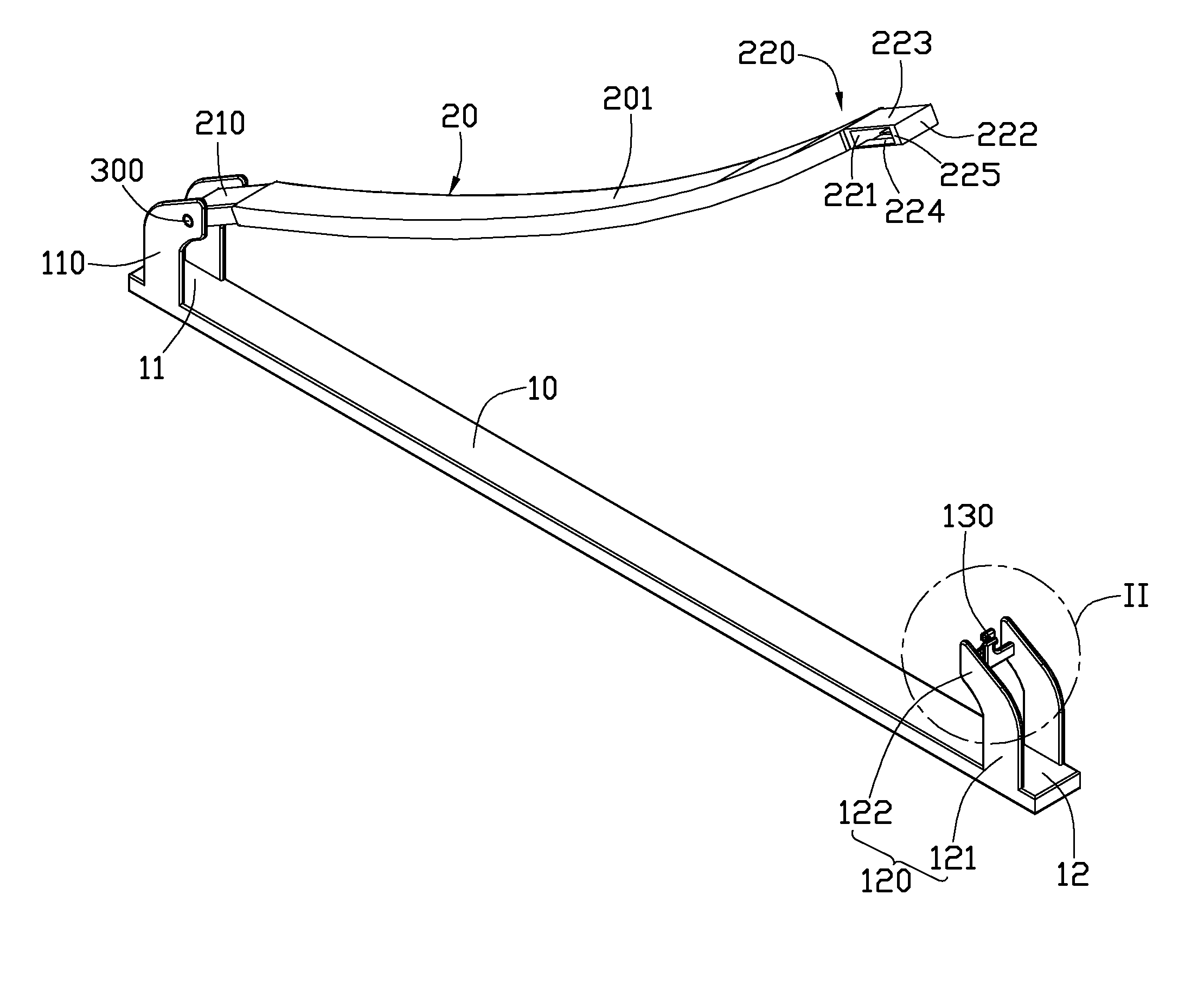
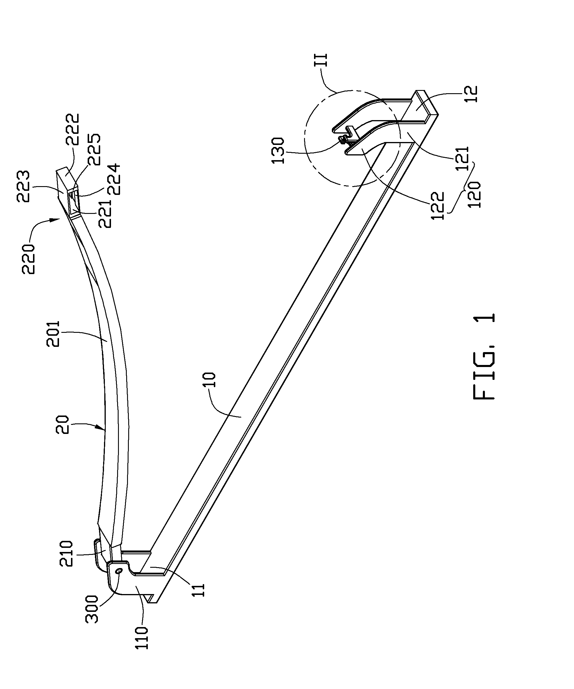
[0012]Referring to FIGS. 1-2, an exemplary embodiment of a wiring clip includes an elongated seat 10 and a pressing member 20 engaged with the seat 10. The wiring clip can be applied in computers or servers to organize wires or cables therein. In the present embodiment, the wiring clip is used to fix wires of a computer to an enclosure of the computer.

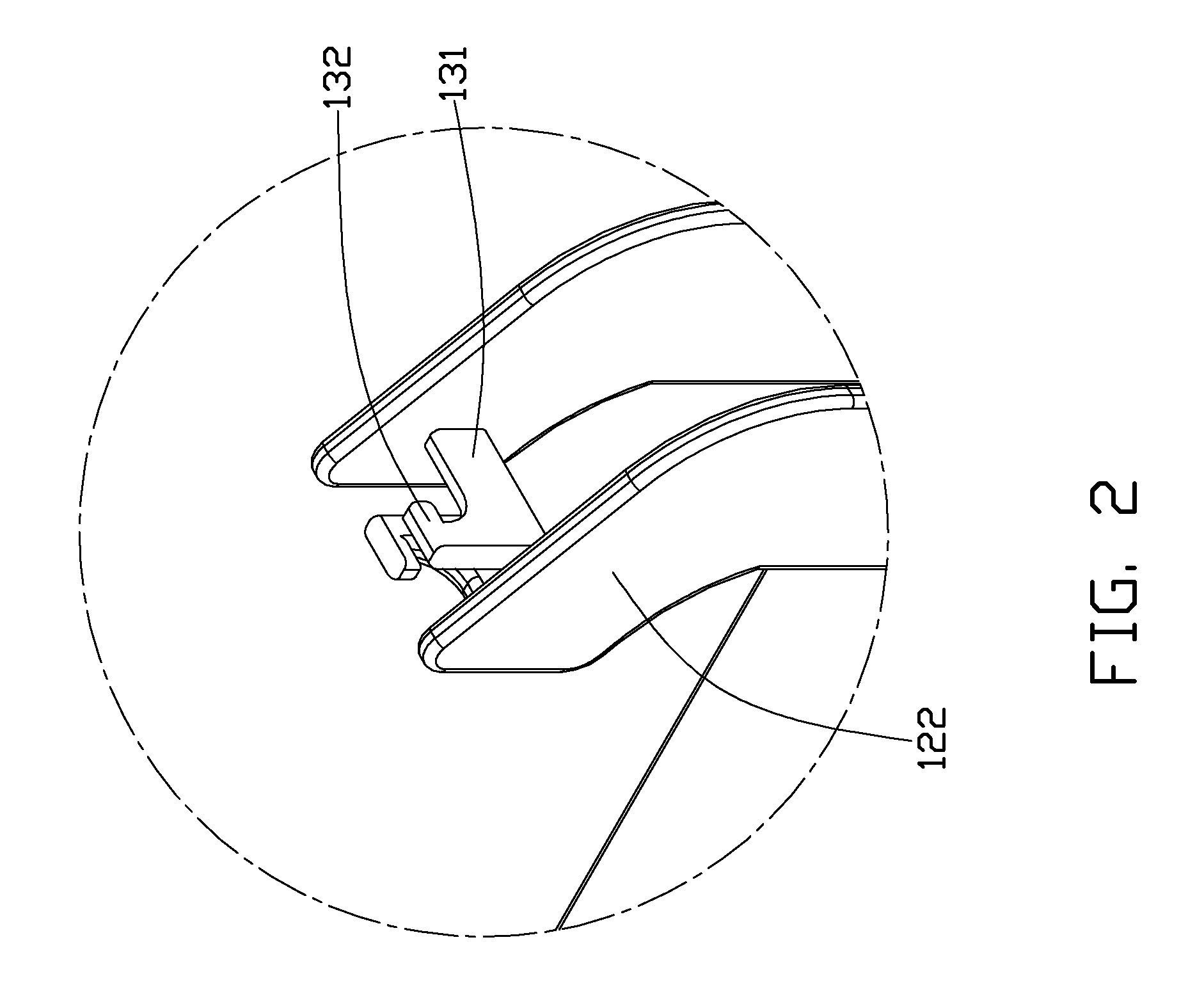
[0013]The seat 10 is fixed to the enclosure of the computer and includes a first end 11 and a second end 12 opposite to the first end 11. Two parallel first sheets 110 extend upwardly from the first end 11 of the seat 10, and another two parallel second sheets 120 extend upwardly from the second end 12 of the seat 10. The pressing member 20 includes a fixing end 210 engaging with the first end 11, a clipping end 220 engaging with the second end 12, and an elastic pressing body 201 between the fixing end 210 and the clipping end 220. The pressing body 201 is an arc-shaped sheet and arches towards the seat 10. A combination structure of ...


PUM


Abstract

A wiring clip includes a seat and a pressing member. The seat has a first end and a second end opposite to the first end. The pressing member includes a fixing end pivotally connected to the first end of the seat, a clipping end engaging with the second end of the seat and a pressing body between the fixing end and the clipping end. Two spaced sheets extend upwardly from the second end of the seat, and two hooks extend inwardly from inner side surfaces of the two sheets. The clipping end defines a first opening, the two hooks extend through the first opening and clasp two sides defining the first opening.

Description

BACKGROUND[0001]1. Technical Field[0002]The disclosure relates to wiring clips and, particularly, to a wiring clip capable of conveniently clipping wires.[0003]2. Description of Related Art[0004]Generally, computers or servers have wiring clips to organize wires electrically connecting electronic elements. A conventional wiring clip includes an elongated sheet defining several through holes at two ends thereof, and several screws engaging with the sheet, thereby fixing the wiring clip to an enclosure of a computer. In use, wires are disposed between the sheet and the enclosure, and the screws are extended through the through holes of the sheet and screwed in the enclosure, thereby fixing the wires to the enclosure. However, having the wiring clip fixed to the enclosure by several screws complicates assembly and disassembly.[0005]What is needed, therefore, is a convenient wiring clip.BRIEF DESCRIPTION OF THE DRAWINGS[0006]Many aspects of the present disclosure can be better understoo...

Claims


Application Information

Patent Timeline
Patent Type & Authority Applications(United States)
IPC IPC(8): F16B2/20
CPCF16B2/20Y10T24/44291H02G3/32H02G3/26
Inventor CHOU, CHIA-SHINYE, ZHEN-XING
Owner HONG FU JIN PRECISION IND (SHENZHEN) CO LTD
Why Eureka
Try Eureka