Methods of assembling an electrical machine

a technology of electrical machines and components, applied in the direction of windings, synchronous machines with stationary armatures, rotating magnets, etc., can solve the problems of high magnetic forces trying to increase eccentricity, complicated stator structure, and general requirement of expensive and voluminous tooling, so as to facilitate the assembly of the rotor or stator

Active Publication Date: 2016-06-30
GE RENEWABLE TECH WIND BV
View PDF11 Cites 1 Cited by
  • Summary
  • Abstract
  • Description
  • Claims
  • Application Information

AI Technical Summary

Benefits of technology

[0031]These second separators between second elements may provide another means to correctly position the second elements tangentially with respect to the first elements.
[0032]In some examples, the attachment of at least one of the second elements to corresponding first elements may be performed before the attachment of said first elements to the rim of the first structure. Some assemblies constituted by permanent magnet elements and winding elements (with or without non-magnetic separators) may therefore be assembled before the attachment of the first elements to the rim of the first structure. Then, said assemblies can be attached to the rim of the first structure by the side of the first elements. This feature may provide certain flexibility to some examples of the constructing method.
[0033]According to examples, attaching the second elements to the rim of the second structure may comprise screwing the second elements to the second structure. An aspect of screwing the second elements is that the thread(s) of the screws, bolts or similar used for that purpose may support strong forces, such as the attraction forces caused by the permanent magnet elements. Hence, screwing may permit overcoming these attraction forces and, therefore, pulling the second elements towards the second structure in a very controlled manner.
[0034]In examples, a permanent magnet element may be a single permanent magnet which may be attached directly to the rim of the first or second structure. Alternatively, a permanent magnet element may be a permanent magnet module comprising a module base and a plurality of permanent magnets coupled to the module base, such that said permanent magnets may be attached together to the rim of the first or second structure through the module base. An aspect of using permanent magnet modules is that the assembly of the rotor or stator can be further facilitated.

Problems solved by technology

The insertion of a rotor of a PM generator carrying already magnetized magnet elements into a pre-assembled stator, i.e. a stator structure plus winding elements and stator core can be complicated due to the high attraction forces generated by the magnets between the stator core and the magnets (i.e. between stator and rotor).
These magnetic forces pull the rotor towards the stator and lead to an inherently unstable situation with respect to the radial centering, i.e. a small eccentricity of the rotor may lead to high magnetic forces trying to increase the eccentricity.
As a result, not only expensive and voluminous tooling is generally required for this operation, but the operation can also entail a significant health and safety risk.
Even though this method of assembly may generally be easier than the previous one, also in this method the magnetic attraction when inserting the permanent magnet modules may cause problems and more so when a number of modules have already been mounted.
Again heavy and costly guiding systems and tools are generally required.
Furthermore, the operation may be time consuming due to the high number of modules to be inserted.
As explained before, the permanent magnet elements generate a magnetic field that can generate attraction forces and can complicate the assembly of an electrical machine in prior art assembling methods.

Method used


Image

  • Methods of assembling an electrical machine
  • Methods of assembling an electrical machine
  • Methods of assembling an electrical machine

Examples


Embodiment Construction

[0039]FIGS. 1a to 8b will be used for describing examples of methods of assembling an electrical machine such as e.g. a generator.

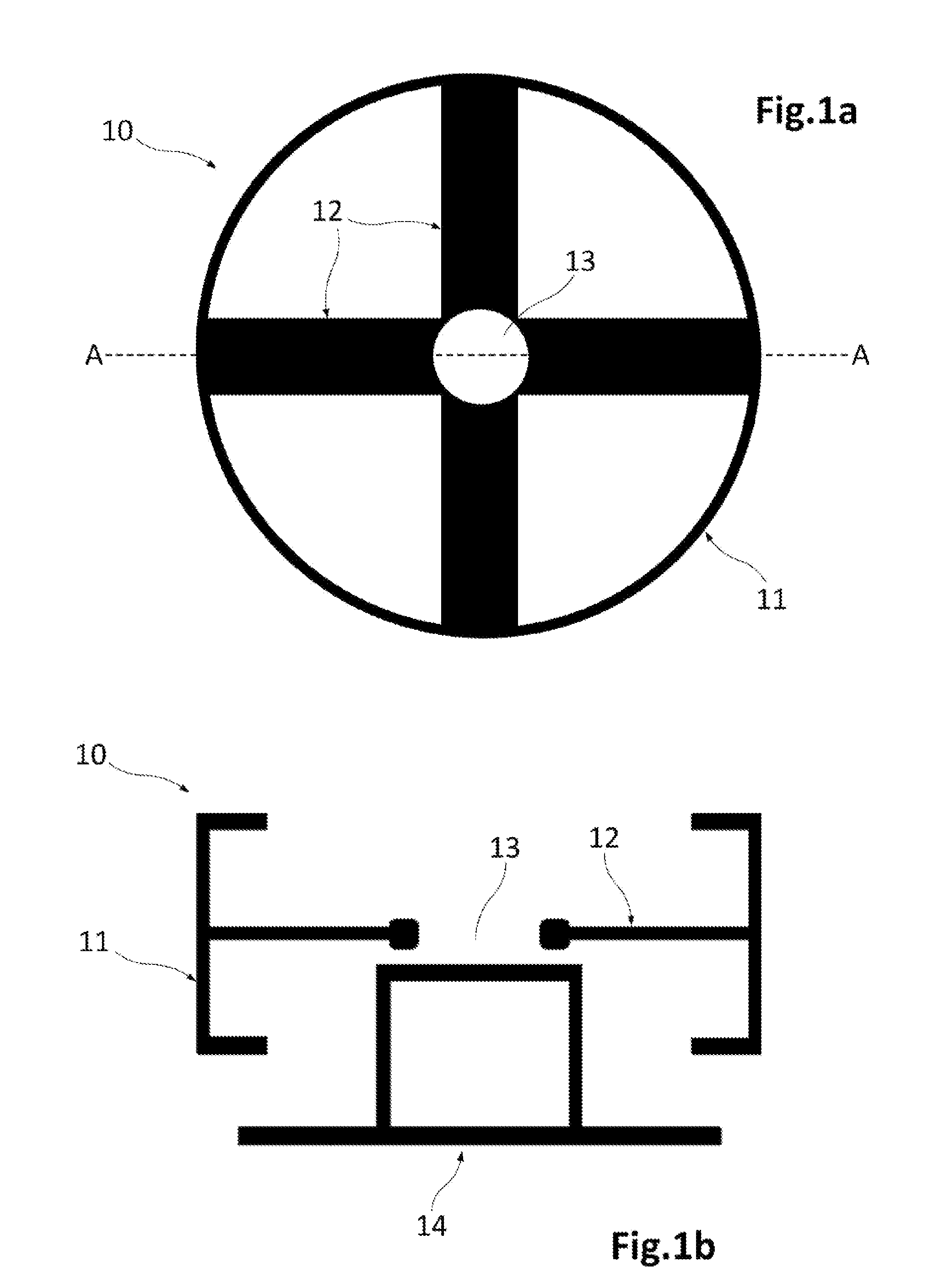
[0040]FIGS. 1a and 1b schematically illustrate an example of rotor structure 10 which has been mounted on a supporting structure 14 such as e.g. a pedestal. FIG. 1a shows the rotor structure 10 which in this example has a rotor rim 11, spokes 12 and a central opening 13 for its coupling with a rotor shaft or with one or more bearings (not shown) depending on the configuration chosen. FIG. 1b is a schematic representation of a cross sectional view of the rotor structure 10 mounted on the pedestal 14 according to a plane AA indicated in FIG. 1a.

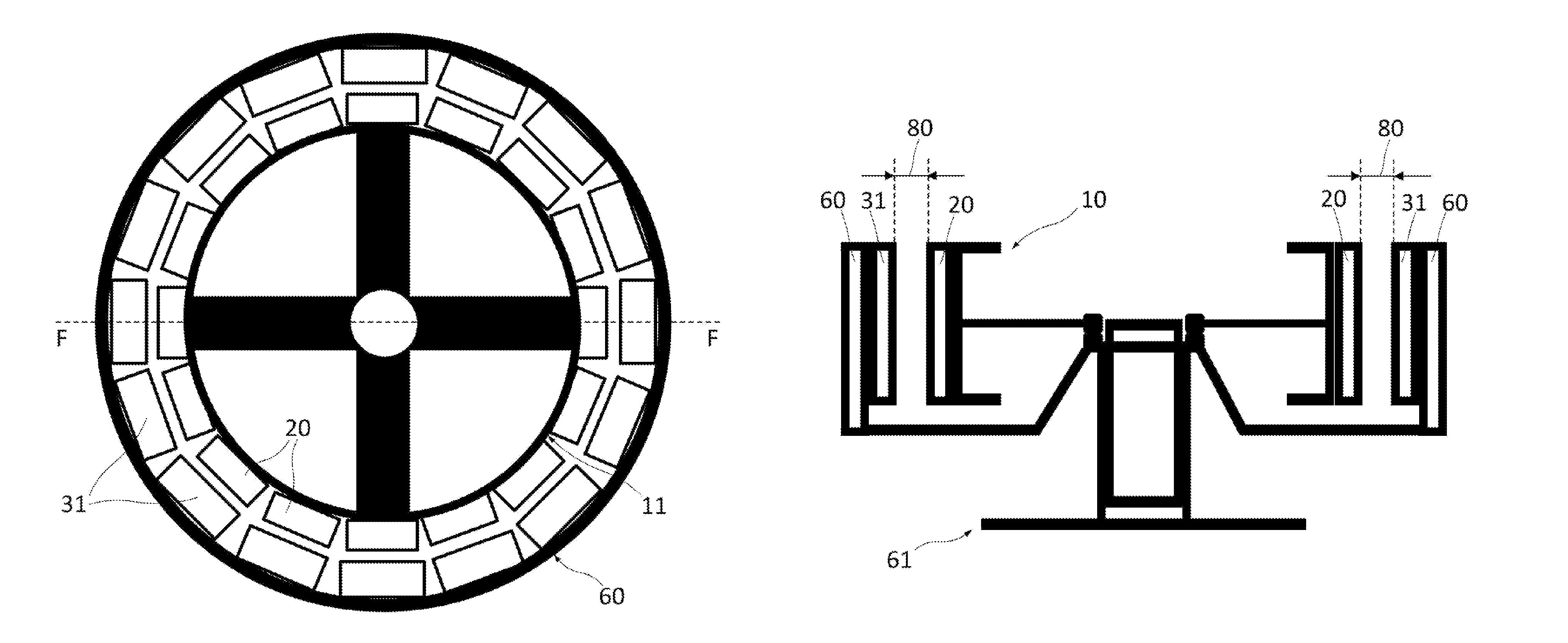
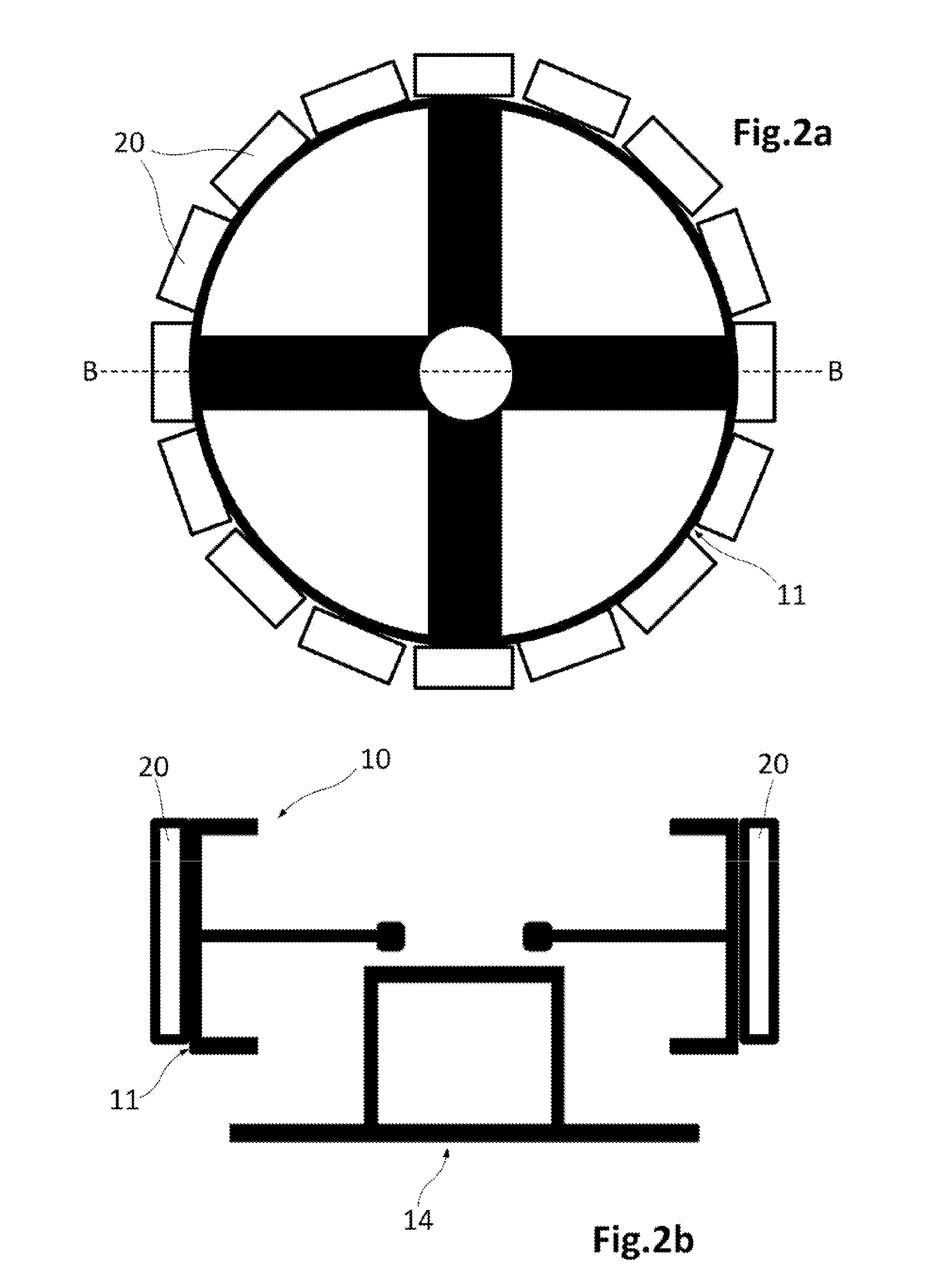
[0041]Once the rotor structure 10 is mounted on the pedestal 14, an arrangement as the one shown in FIGS. 2a and 2b can be obtained. This arrangement may result from attaching a plurality of permanent magnet elements 20 to the rim 11 of the rotor structure 10. FIG. 2a is a schematic illustration of a top view of the...


PUM

PropertyMeasurementUnit
thicknessaaaaaaaaaa
thicknessaaaaaaaaaa
thicknessaaaaaaaaaa

Abstract

A method of constructing an electrical machine by assembling a first structure (one of a rotor and stator structure) and a second structure (the other of the rotor and stator structure), along with a plurality of first elements (one of a plurality of permanent magnet elements and a plurality of winding elements) and a plurality of second elements (the other plurality of the permanent magnet elements and winding elements). The first elements are attached to a rim of the first structure, and the second elements are attached to the first elements, this attachment being caused by a magnetic attraction. The first structure is assembled with the second structure such that the second elements are positioned for a posterior attachment to a rim of the second structure, and the second elements are attached to the rim of the second structure.

Description

[0001]The present disclosure relates to methods for assembling electrical machines. This application claims priority to European Application No. 14382570.1, filed Dec. 24, 2014, the entire contents of which are hereby incorporated by reference.BACKGROUND ART[0002]Electrical machines generally comprise a rotor structure and a stator structure. In case of permanent magnet excited generators (PMG) permanent magnets (PM) are generally comprised in the rotor (although they could also be arranged alternatively in the stator structure), whereas winding elements (e.g. coils) are usually included in the stator (although they could alternatively be arranged in the rotor structure).[0003]The insertion of a rotor of a PM generator carrying already magnetized magnet elements into a pre-assembled stator, i.e. a stator structure plus winding elements and stator core can be complicated due to the high attraction forces generated by the magnets between the stator core and the magnets (i.e. between s...

Claims


Application Information

Patent Timeline
Patent Type & Authority Applications(United States)
IPC IPC(8): H02K15/16H02K15/06
CPCH02K15/06H02K15/16H02K15/028H02K15/03H02K2213/12Y10T29/49009Y10T29/49012Y10T29/49069Y10T29/49073Y02E10/72H02K1/2791H02K1/278H02K3/46H02K1/274H02K35/02H02K21/22H02K21/12H02K21/227
Inventor KELLER, STEFAN
Owner GE RENEWABLE TECH WIND BV
Why Eureka
Try Eureka