
Support mechanism with mounting member rotatingly received in support seat

a technology of supporting mechanism and mounting member, which is applied in the direction of stand/trestle, display means, instruments, etc., can solve the problem of complicated assembly of the supporting mechanism

Inactive Publication Date: 2012-12-06
HONG FU JIN PRECISION IND (SHENZHEN) CO LTD +1
View PDF9 Cites 0 Cited by
  • Summary
  • Abstract
  • Description
  • Claims
  • Application Information

AI Technical Summary

Benefits of technology

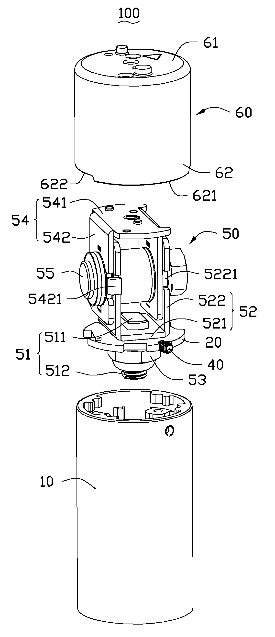
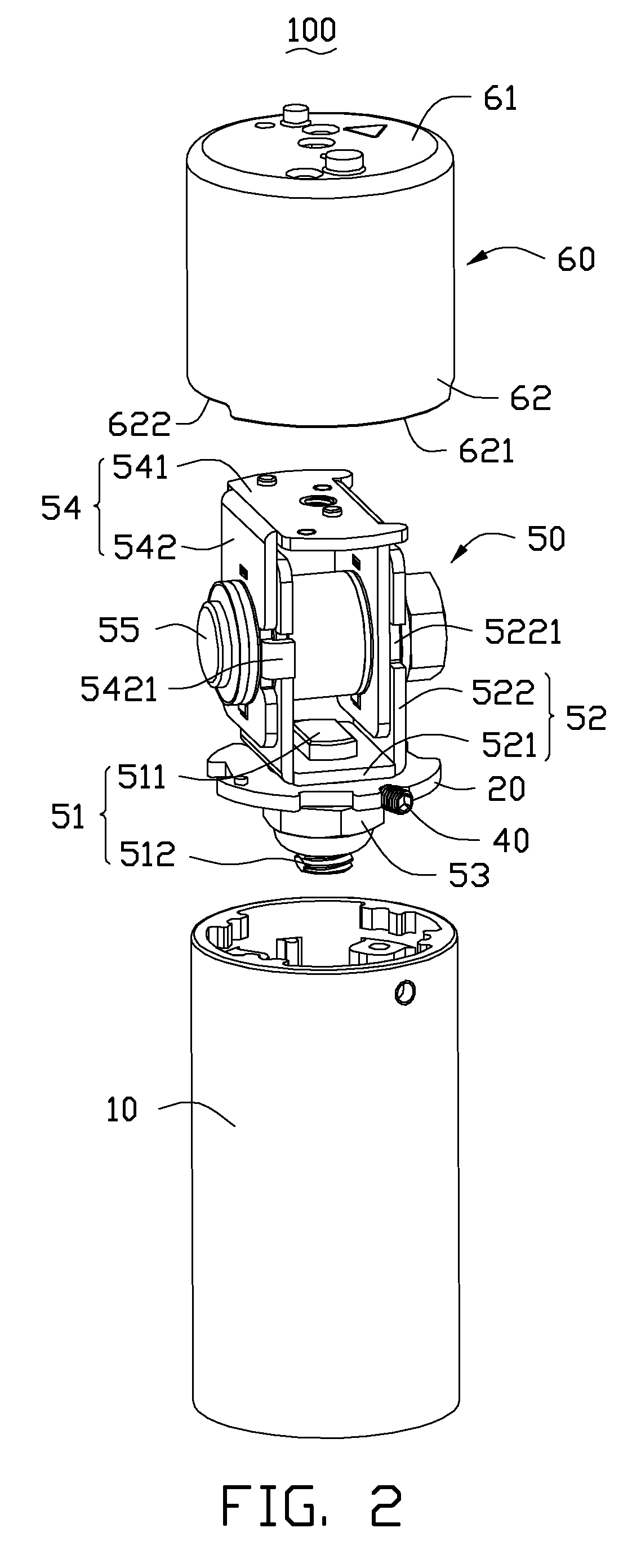
[0004]A commonly used display device includes a display panel, a base seat and a support mechanism. The display panel connects with the base seat via the support mechanism, and the display panel is able to be viewed from many different angles by adjusting its position. The support mechanism generally includes a support seat, a mounting member, and a hinge assembly connected to the mounting member. The base seat may be fixed to a desk or a wall in a room, and the support seat is fixed to the base seat. The mounting member defines two positioning holes and a plurality of through holes. The support seat includes two positioning posts and defines a plurality of screw holes. The two positioning posts extend into the two positioning holes, and the screw holes are aligned with the through holes. Then a plurality of screws is received in the through holes and the screw holes such that the mounting member is fixed to the support seat. Typically, the support mechanism defines many screw holes and the two positioning holes, and requires many screws for assembly. This makes the assembly of the support mechanism complicated.

Problems solved by technology

This makes the assembly of the support mechanism complicated.

Method used


Image

  • Support mechanism with mounting member rotatingly received in support seat
  • Support mechanism with mounting member rotatingly received in support seat
  • Support mechanism with mounting member rotatingly received in support seat

Examples


Embodiment Construction

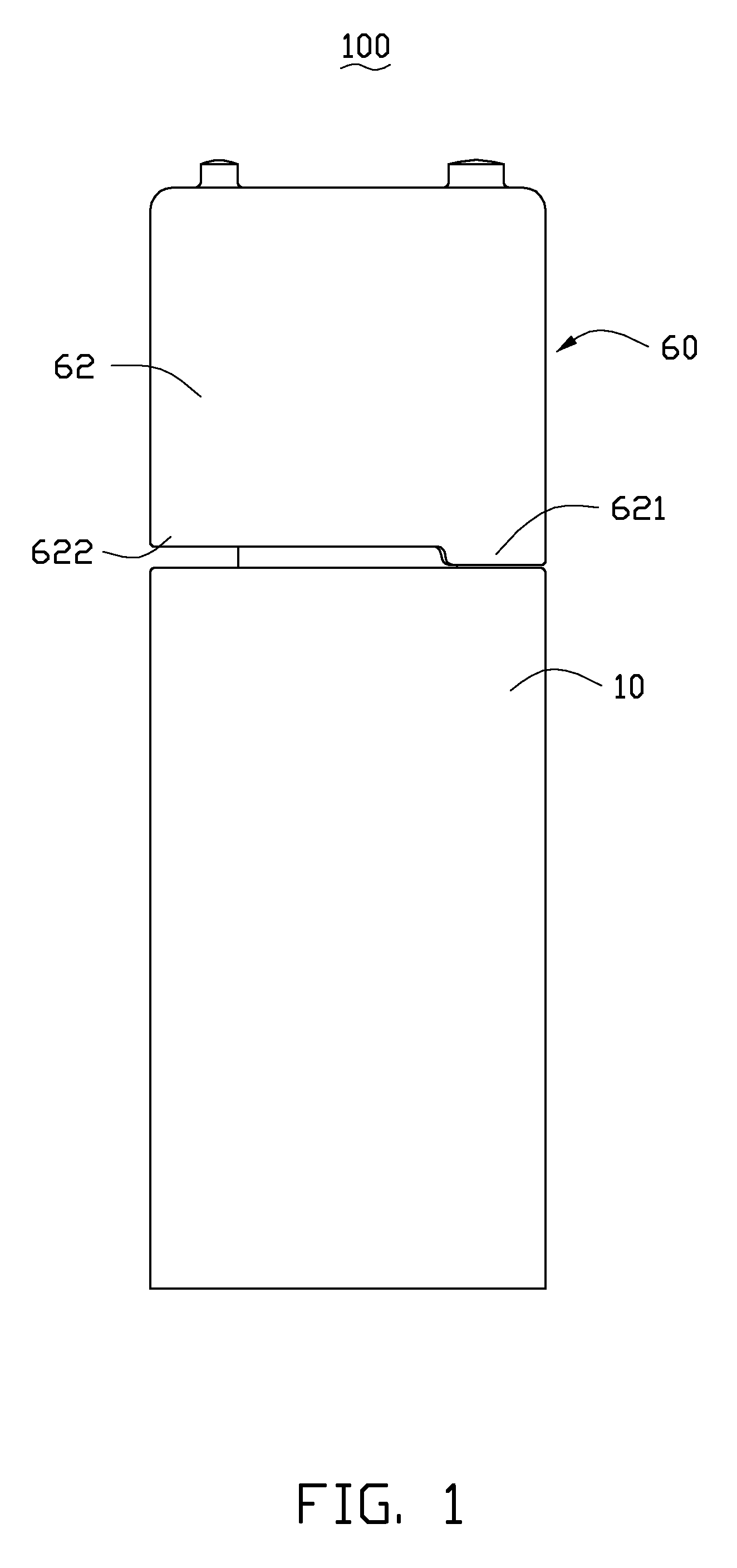
[0014]Referring to FIGS. 1-3 and 5, an embodiment of a support mechanism 100 includes a support seat 10, a mounting member 20, a fixing member 30, a positioning member 40, a hinge assembly 50, and a connecting sleeve 60. The support seat 10 includes a mounting end 11 and a fixing end 12 opposite to the mounting end 11. The mounting member 20 is fixed to the mounting end 11 of the support seat 10 by the positioning member 40. The fixing member 30 is connected to the fixing end 12 of the support seat 10. The hinge assembly 50 is connected to the mounting member 20. The connecting sleeve 60 is sleeved on the hinge assembly 50. In the present embodiment, the support mechanism 100 is used for a flat screen television. The connecting sleeve 60 is connected to a display panel of the flat screen television, and the fixing member 30 is fixed to a base of the flat screen television. The support mechanism 100 allows the position of the display panel to be adjusted so that the display panel is ...


PUM


Abstract

A support mechanism includes a hinge assembly, a hollow support seat, a positioning member and a mounting member. The support seat includes a plurality of restricting portions and a plurality of support portions corresponding to the restricting portions, the restricting portions and the support portions cooperatively defining a receiving space therebetween. The support seat further defines a positioning hole in the circumferential wall thereof, the positioning hole communicating with the receiving space. The positioning member is received in the positioning hole. The mounting member is connected to the hinge assembly and includes a peripheral position portion, the position portion is capable of passing the restricting portions when inserted into the support seat and rotating within the receiving space to a predetermined position in which the positioning member is engagable with the position portion of the mounting member to fix the hinge assembly to the support seat.

Description

BACKGROUND[0001]1. Technical Field[0002]The present disclosure relates to support mechanisms, and more particularly, to a support mechanism used for supporting a display panel.[0003]2. Description of Related Art[0004]A commonly used display device includes a display panel, a base seat and a support mechanism. The display panel connects with the base seat via the support mechanism, and the display panel is able to be viewed from many different angles by adjusting its position. The support mechanism generally includes a support seat, a mounting member, and a hinge assembly connected to the mounting member. The base seat may be fixed to a desk or a wall in a room, and the support seat is fixed to the base seat. The mounting member defines two positioning holes and a plurality of through holes. The support seat includes two positioning posts and defines a plurality of screw holes. The two positioning posts extend into the two positioning holes, and the screw holes are aligned with the t...

Claims


Application Information

Patent Timeline
Patent Type & Authority Applications(United States)
IPC IPC(8): G09F15/00
CPCF16M11/08F16M13/027F16M13/02F16M11/105
Inventor YANG, ZHEN-YU
Owner HONG FU JIN PRECISION IND (SHENZHEN) CO LTD
Learn More