
Curved functional film structure and method for producing same

a functional film and shape technology, applied in the field of three-dimensional shape functional film structure, can solve the problems that the prior art does not disclose a structure in which pressure- or temperature-sensitive buttons have been made into three-dimensional shapes, and achieve the effects of increasing sensitivity, reducing size, and increasing sensitivity

Pending Publication Date: 2022-02-03
JOANNEUM RES FORSCHUNGS GMBH +2
View PDF0 Cites 1 Cited by
  • Summary
  • Abstract
  • Description
  • Claims
  • Application Information

AI Technical Summary

Benefits of technology

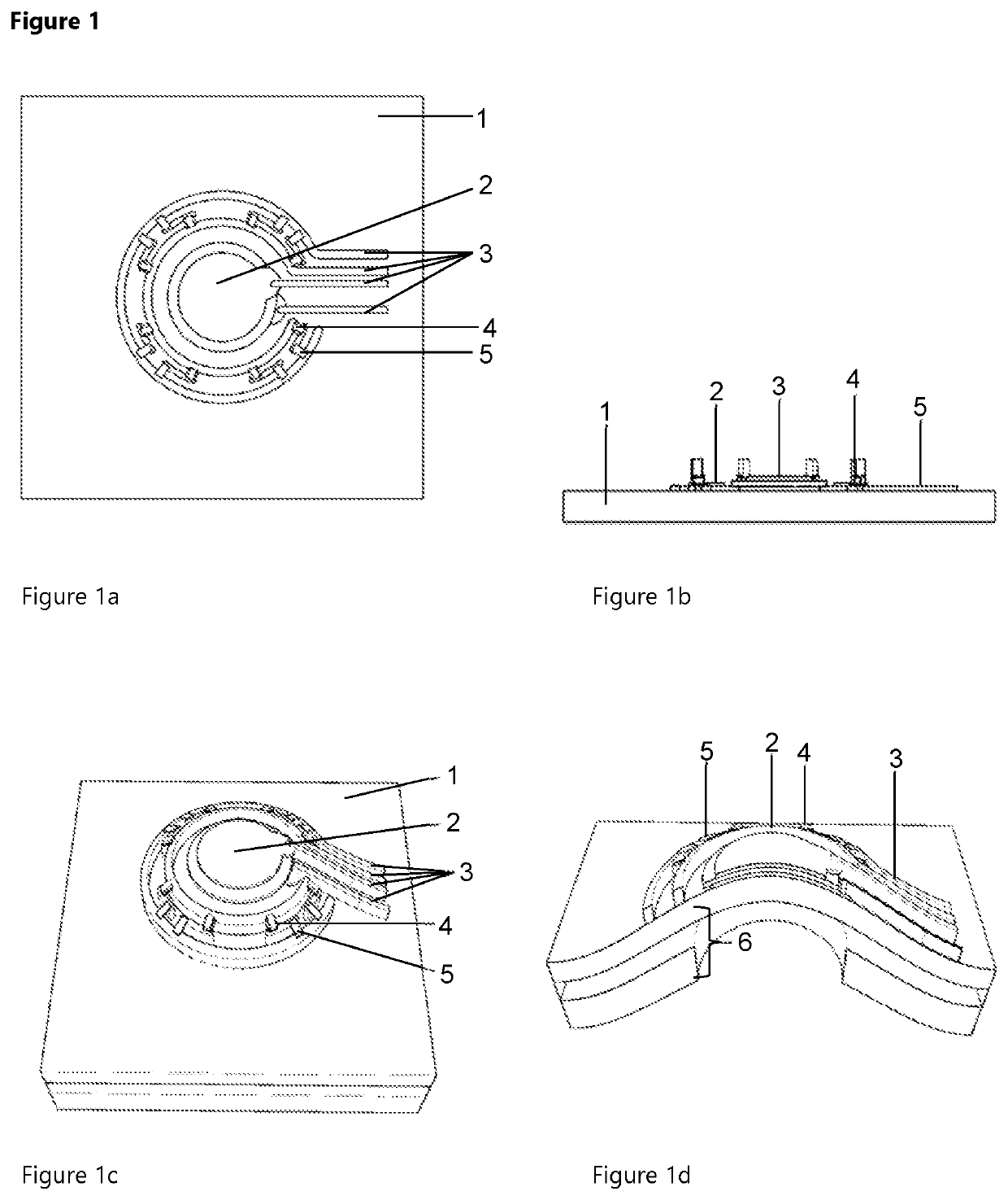
The invention is a functional film structure that includes a curved sensor, which increases its sensitivity and reduces its size compared to a planar sensor. The structure also includes a haptic structure to support the tactility of the sensor elements. This design is suitable for use as a button or button array with a seamless surface in control panels. The structure is high pressure or temperature sensitive to react to different button pressure levels or the approach of a person and generate a proportional electrical signal. The membrane keypads are advantageous due to their low susceptibility to soiling, high durability, and adaptability. The structure is also advantageous for its low cost-effectiveness, environmental balance, and intuitive operation. The structure has a high formability, which allows for simpler production and assembly, and can be partially transparent for illumination or backlighting of the button.

Problems solved by technology

However, the prior art does not disclose a structure in which pressure- or temperature-sensitive buttons have been made into a three-dimensional shape.

Method used


Image

  • Curved functional film structure and method for producing same
  • Curved functional film structure and method for producing same

Examples


example 1

[0184]Sensor buttons having diameters of 10 mm, 15 mm and 20 mm were provided on a thermoplastic deformable film substrate (PMMA film, thickness: 175 μm). The round buttons were made of sufficiently transparent materials in sandwich construction having a base electrode layer, a ferroelectric sensor layer and a cover electrode layer. The electrical contact to the outside was made via ring-shaped conductor paths. For backlighting, LED light sources were mounted outside the actual sensing section. The integration of the LEDs directly next to the sensor section required a very small design of the LEDs. These were provided using pico-LEDs (SMD components) with very small dimensions (1 mm×0.6 mm) and a low thickness of 0.2 mm. The illumination of the sensor buttons was examined in advance using optical simulations with a commercial ray-tracing tool (OpticStudio). Based on the simulations, a sufficient number of pico-LEDs and an equivalent number of series resistors were placed outside the...

example 2

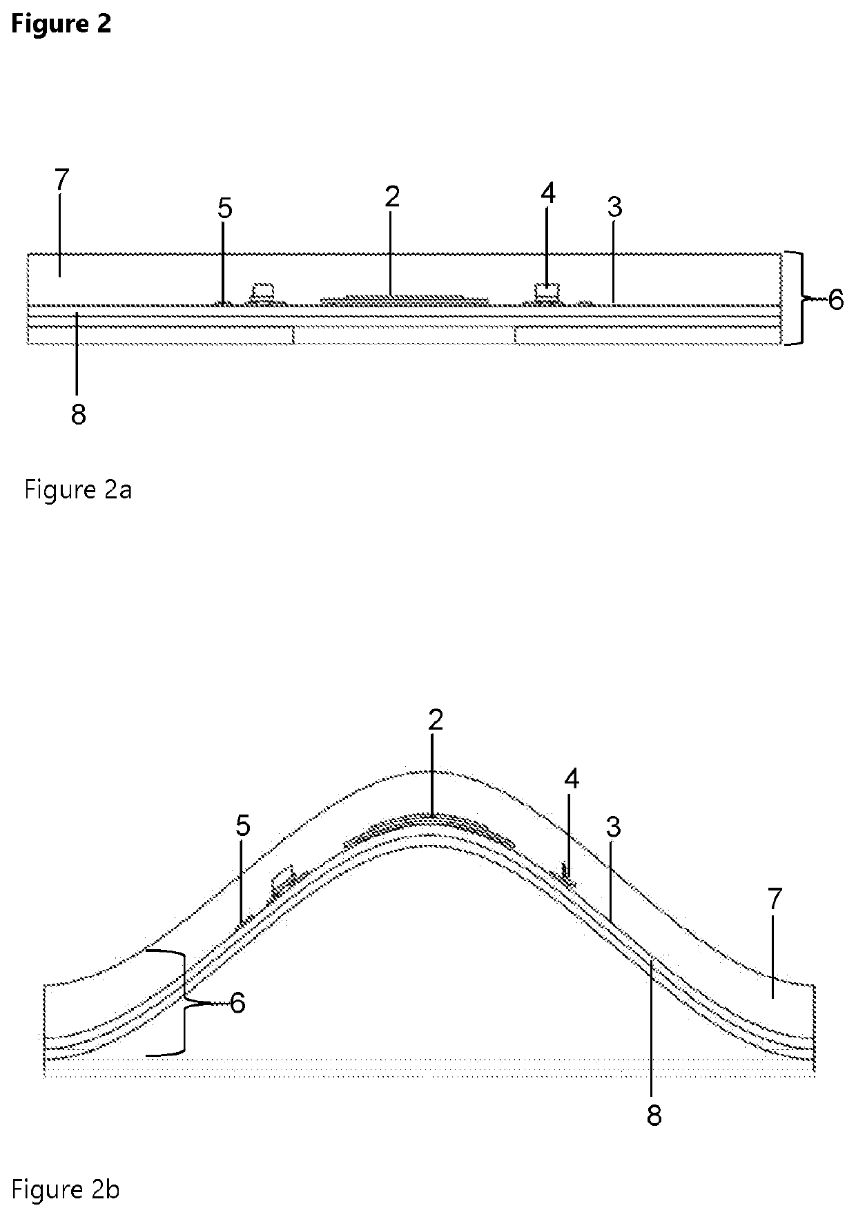
[0188]This example describes a method of manufacturing a backlit pressure or temperature sensitive film sensor button having a three-dimensional shape (see FIG. 2).

[0189]First, a film composite was produced. The two-dimensional bonding of the functional film (e.g. PEN) and the carrier film (e.g. ABS) was carried out by means of a wet lamination process in a roll-to-roll procedure. In the laminating process, a liquid laminating adhesive was first applied to one of the two films, pre-dried and the film thus coated was then bonded to the other film under the effect of pressure and / or temperature.

[0190]Then, the film sensor button was produced. The individual layers of the film sensor button (sensor sandwich, conducting paths) and the decorative ink were applied in a structured manner to a pre-cut film composite (e.g. PEN / ABS) using an additive screen printing process including intermediate drying through a mask (screen / template). The printing sequence was as follows: On the printable P...


PUM

PropertyMeasurementUnit
areaaaaaaaaaaa
pressureaaaaaaaaaa
pressureaaaaaaaaaa

Abstract

The present invention provides a functional film structure and a method of manufacturing the same. The functional film structure has a sensor button arranged on a film substrate and can be formed into a three-dimensional shape by thermal forming processes such as vacuum deep-drawing or high-pressure moulding. The functional film structure is preferably flexible and preferably has transparent and illuminated sections.

Description

FIELD OF THE INVENTION[0001]The present invention relates to a three-dimensionally shaped functional film structure with a sensor unit and a method of manufacturing the same.STATE OF THE ART[0002]Currently, film surfaces are often provided with functions in the field of structural electronics, in-mold electronics and three-dimensional (3D) integrated electronics. The functional films are then formed into a three-dimensional shape or backmoulded in a Foil Insertion Moulding process (FIM) and thus mechanically stabilised. Examples of this are the European project TERASEL1, in which several FIM demonstrators were provided, such as the 3D integration of LEDs on a three-dimensional plastic calotte or a plate with homogeneously illuminated recesses based on integrated LEDs. There is also a back-moulded LED display or a luminous flexible wristband on the market, where the LEDs are first placed on stretchable substrates using pick-and-place and then slightly deformed. This is followed by ov...

Claims


Application Information

Patent Timeline
Patent Type & Authority Applications(United States)
IPC IPC(8): B29C51/08H05K1/18H05K3/00H05K3/46H05K3/30B29C51/14G01L9/00G01K7/16B60K35/10
CPCB29C51/08H05K1/18H05K3/0011H05K3/4644H05K3/305B29L2031/3406G01L9/0041G01K7/16H05K2201/10151H05K2201/10106B29C51/14H03K17/962B29L2031/3443H05K3/0014H05K1/0284H03K2217/960755H05K1/181H05K3/1216H05K2203/1105H05K1/16B29C45/14639
Inventor STADLOBER, BARBARABELEGRATIS, MARIASCHMIDT, VOLKERZIRKL, MARTINSCHEIPL, GREGORTRASSL, STEPHANGSCHWANDTNER, ANDREASPADINGER, FRANZHEILMANN, MICHAELIDE, DIRK
Owner JOANNEUM RES FORSCHUNGS GMBH
Learn More