Method for fabricating battery shell

a battery shell and fabrication method technology, applied in the field of battery shells, can solve the problems of increased working hours and costs, unfavorable, and too large battery shells,

Inactive Publication Date: 2016-03-08
GETAC TECH CORP
View PDF8 Cites 0 Cited by
  • Summary
  • Abstract
  • Description
  • Claims
  • Application Information

AI Technical Summary

Benefits of technology

[0005]However, the above manufacturing method needs corresponding room in the battery shell to contain the metal contacts and the insulating material. As a result, the size of the battery shell may be too large and not unfavorable for the miniaturization of the electronic device. Furthermore, the above method may complicate the assembly of a battery module, and thus the working hours and cost may increase.

Problems solved by technology

However, the above manufacturing method needs corresponding room in the battery shell to contain the metal contacts and the insulating material.
As a result, the size of the battery shell may be too large and not unfavorable for the miniaturization of the electronic device.
Furthermore, the above method may complicate the assembly of a battery module, and thus the working hours and cost may increase.

Method used


Image

  • Method for fabricating battery shell
  • Method for fabricating battery shell
  • Method for fabricating battery shell

Examples


first embodiment

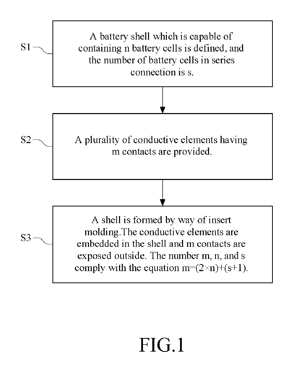
[0022]FIG. 1 is a flowchart of a method for fabricating a battery shell according to the disclosure.

[0023]The method comprises the following steps.

[0024]A battery shell which is capable of containing n battery cells is defined, and the number of battery cells in series connection is s (S1).

[0025]A plurality of conductive elements are provided, and the conductive elements have m contacts (S2). Herein n, s, and m are all positive integers.

[0026]A shell is formed by way of insert molding, and the conductive elements are embedded in the shell and the m contacts are exposed outside. Furthermore, the number m, n, and s comply with the equation (1).

m=(2×n)+(s+1)  (1) (S3)

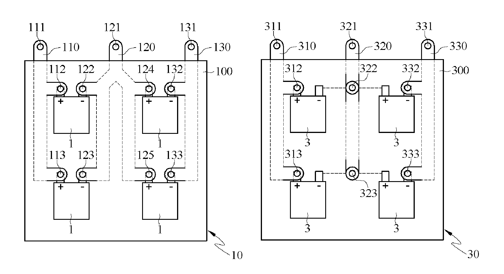
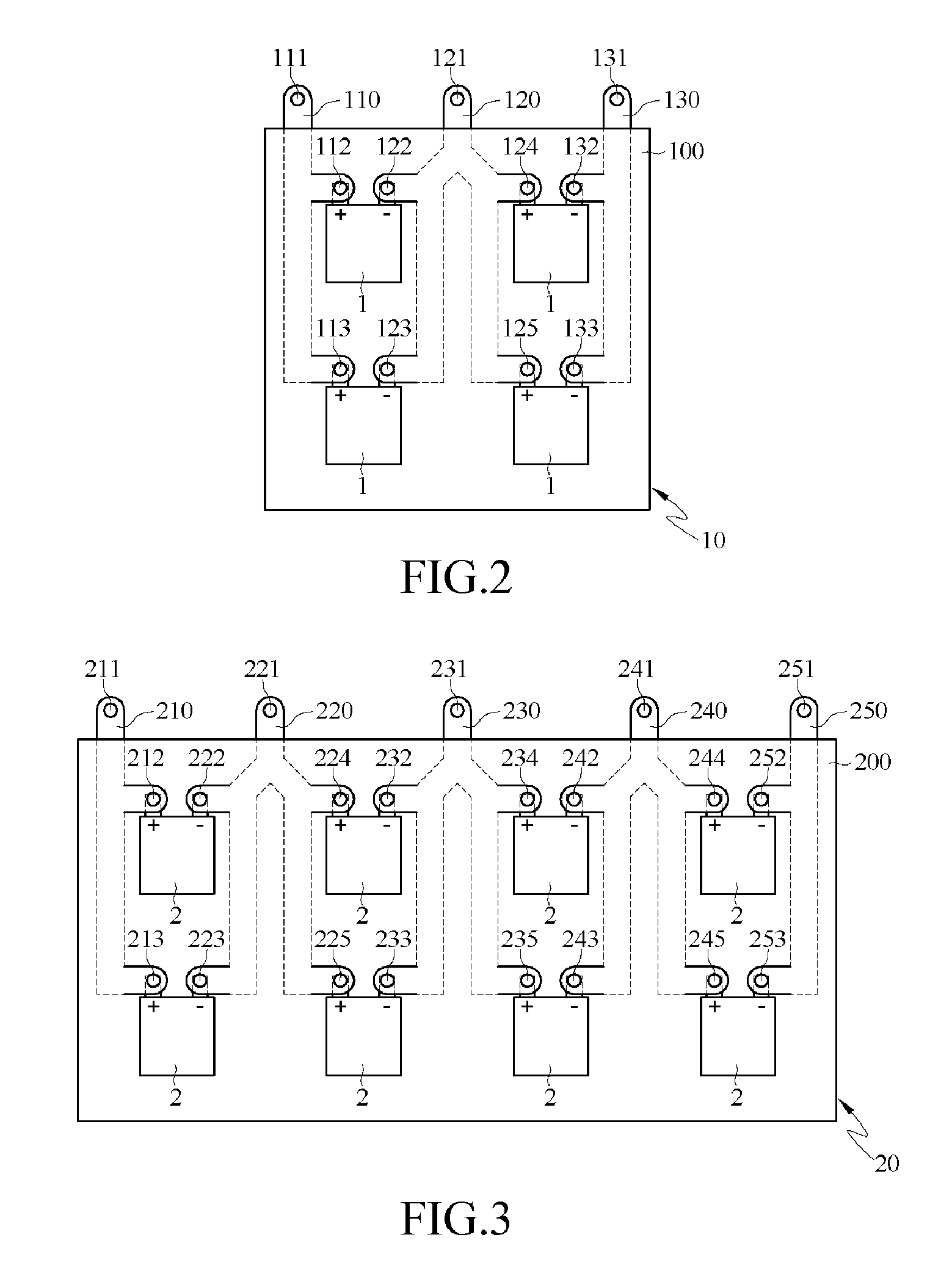
[0027]FIG. 2 is a structural diagram of a battery shell which is fabricated by the method of the first embodiment.

[0028]With reference to FIG. 2, the battery shell 10 can be used in a laptop, but it is not limited this way. The battery shell 10 comprises 4 battery cells 1. The number of battery cells 1 in series connection...

second embodiment

[0040]FIG. 5 is a structural diagram of a battery shell which is fabricated by the method of the

[0041]With reference to FIG. 5, the battery shell 30 can be used in a laptop, but it is not limited this way. The battery shell 30 comprises 4 battery cells 3. The number of battery cells 3 in series connection is two, and the number of battery cells 3 in parallel connection is also two.

[0042]The battery shell 30 comprises a casing 300, a first conductive element 310, a second conductive element 320, and a third conductive element 330. The first conductive element 310, the second conductive element 320, and the third conductive element 330 may be made of copper or nickel material, while the casing 300 may be made of insulation plastic. The first conductive element 310, the second conductive element 320, and the third conductive element 330 are embedded in the casing 300 by way of insert molding. The first conductive element 110 has a power source contact 311 and two positive pole contacts...

third embodiment

[0049]FIG. 8 is a flowchart of a method for fabricating a battery shell according to the disclosure.

[0050]The method comprises the following steps.

[0051]A battery shell which is capable of containing n battery cells is defined, and the number of the battery cells in series connection is s, where s is an odd integer (S1).

[0052]A plurality of conductive elements are provided, and the conductive elements have m contacts (S2). Herein n, s, and m are all positive integers.

[0053]A shell is formed by way of insert molding, and the conductive elements are embedded in the shell and the m contacts are exposed outside. Furthermore, the number m, n, and s comply with the equation (3).

m=(1.5×n)+(s+1+0.5p)  (3) (S3)

[0054]FIG. 9 is a structural diagram of a battery shell which is fabricated by the method of the third embodiment.

[0055]With reference to FIG. 9, the battery shell 50 can be used in a laptop, but it is not limited this way. The battery shell 50 comprises 6 battery cells 5. The number o...


PUM

PropertyMeasurementUnit
conductiveaaaaaaaaaa
insulatingaaaaaaaaaa
sizeaaaaaaaaaa

Abstract

A non-contact input apparatus for computer peripheral includes an induction module and a pointing module. The induction module includes an electric supply coil and an induction element, and the pointing module includes an energy coil and a non-linear element. The electric supply coil is used to send a first oscillation signal. The energy coil receives the first oscillation signal. The non-linear element converts the first oscillation signal to be a second oscillation signal having multiple higher harmonics. The induction element generates a control signal based on the second oscillation signal.

Description

BACKGROUND[0001]1. Technical Field[0002]The disclosure relates to a battery shell, and more particularly to a battery shell where the conductive elements are embedded in the shell.[0003]2. Related Art[0004]Generally, during the manufacturing process of the battery module of an electronic product, a plurality of battery cells and a plurality of metal contacts are electrically combined beforehand to form series connection and parallel connection. Then, the combined battery cells and metal contacts together with the insulating material are packaged in a battery shell to form a battery module.[0005]However, the above manufacturing method needs corresponding room in the battery shell to contain the metal contacts and the insulating material. As a result, the size of the battery shell may be too large and not unfavorable for the miniaturization of the electronic device. Furthermore, the above method may complicate the assembly of a battery module, and thus the working hours and cost may i...

Claims


Application Information

Patent Timeline
Patent Type & Authority Patents(United States)
IPC IPC(8): B29C45/14H01M2/10H01M2/20H01M50/227H01M50/51H01M50/522
CPCH01M2/1022H01M2/204Y02E60/10H01M50/227H01M50/522H01M50/51
Inventor CHAO, PO-TSUN
Owner GETAC TECH CORP
Why Eureka
Try Eureka