Optical Telescope Sight Combining Dot Sight Mode and Scope Mode

a technology of optical telescope and scope mode, which is applied in the direction of telescopes, instruments, weapons, etc., can solve the problems of narrow field of view, difficult to align the line of sight, and complicated aimed shooting methods

Active Publication Date: 2011-05-05
JUNG IN
View PDF6 Cites 22 Cited by
  • Summary
  • Abstract
  • Description
  • Claims
  • Application Information

AI Technical Summary

Benefits of technology

[0046]In accordance with an aspect of the present invention, there is provided an optical device for both a dot sight mode and a scope mode, in which a scope structure is installed to be retractable inside a dot sight device and thus both the dot sight mode and the scope mod...

Problems solved by technology

However, even a small shock or shake makes it difficult to align the line of sight, and it is disadvantageous for quick aiming requested at a short distance or in an urgent situation.
That is, an aimed-shooting method requires complicated procedures and time to acquire and ascertain a target, align the line of sight, aim at the target, etc.
Also, because the front sight and the rear sight themselves are very small, not only they are susceptible to even a small shake, but also eyes are turned upon the front sight and the rear sight rather than the target or a frontward situation and therefore a f...

Method used


Image

  • Optical Telescope Sight Combining Dot Sight Mode and Scope Mode
  • Optical Telescope Sight Combining Dot Sight Mode and Scope Mode
  • Optical Telescope Sight Combining Dot Sight Mode and Scope Mode

Examples


Embodiment Construction

[0117]Next, an optical device for both a dot sight mode and a scope mode according to a second exemplary embodiment of the present invention will be described.

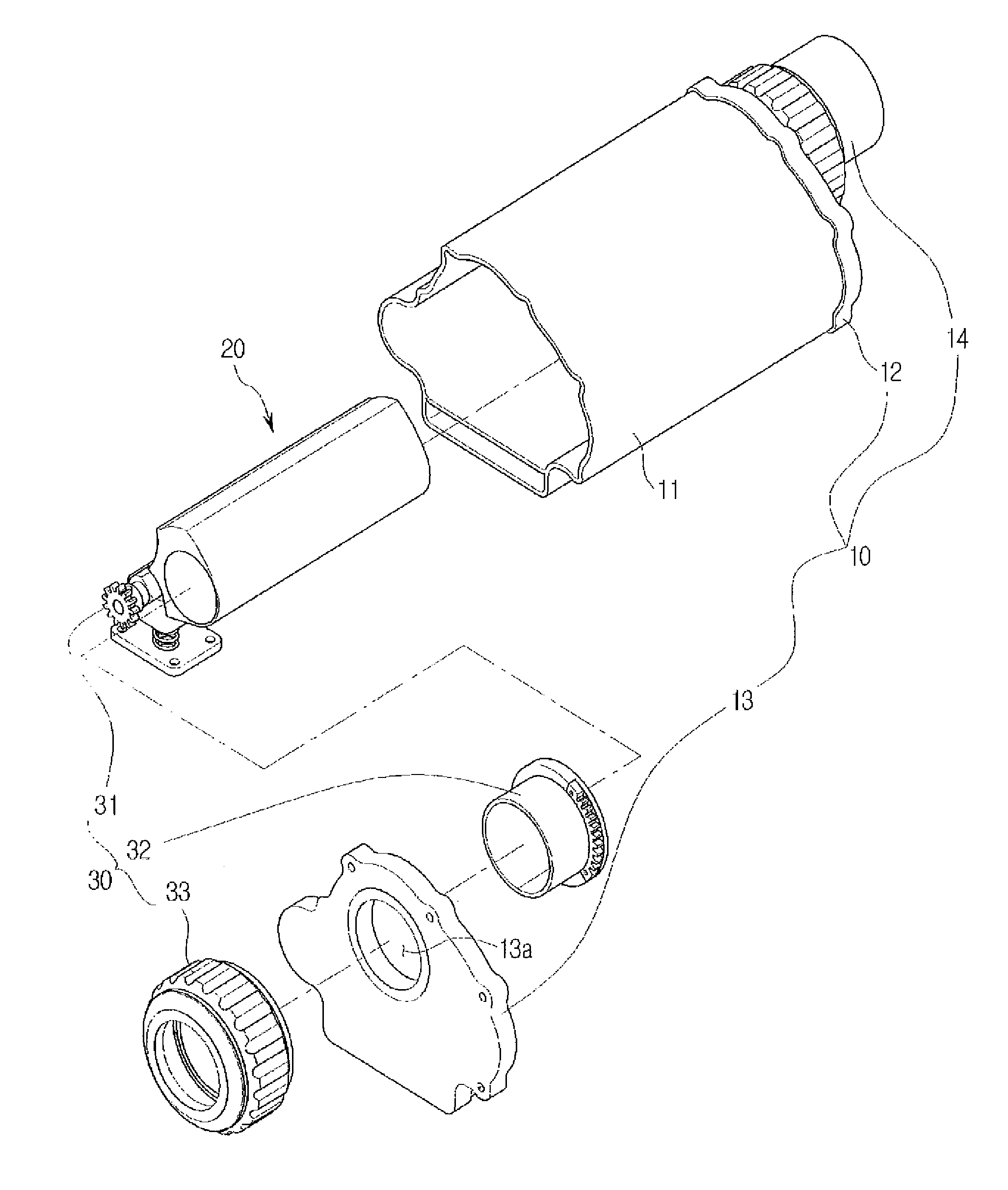
[0118]The optical device of the second exemplary embodiment is the same as that of the first exemplary embodiment except that the position control means is omitted, and the shapes of the rotation means and the boss unit of the scope tube body are changed. FIG. 11 is a schematic view of an optical device for both a dot sight mode and a scope mode according to a second exemplary embodiment of the present invention.

[0119]Referring to FIG. 11, the boss unit 23 is formed with a recessed supporting groove 23b.

[0120]At this time, the rotation means 50 includes an elastic member 51 and a rotation unit 53. The elastic member 51 is a predetermined spring coupled to the scope shaft 24, which includes one side supported by the tube body housing 11 and the other side supported by a support pin 51a protruding from the boss unit 23.

[0121]Th...


PUM


Abstract

The present invention relates to an optical device for both a dot sight mode and a scope mode, the optical device including: a dot-sight main body which is formed with a dot sight region where a light source and a reflective mirror are installed to display light emitted from the light source as a dot on an external target, and operates in the dot sight mode; and a scope structure which includes an objective lens and an eyepiece lens to magnify and see the external target, and is rotatable inside the dot-sight main body, the scope mode being selected when the scope structure is rotated and inserted in the dot sight region. With this, there is provided an optical device for both a dot sight mode and a scope mode, in which a scope structure is installed to be retractable inside a dot sight device and thus both the dot sight mode and the scope mode are supported, thereby aiming at an external target through quick mode switching, and there is no need for an additional scope device.

Description

TECHNICAL FIELD[0001]The present invention relates to an optical device for both a dot sight mode and a scope mode, and more particularly, to an optical device for both a dot sight mode and a scope mode, in which the dot sight mode and the scope mode can be easily switched to each other.BACKGROUND ART[0002]Generally, an optical device may be coupled to one side of a firearm so as to accurately aim an external target. In a particular case of a rifle among the firearms, aiming is achieved by aligning a line of sight between a front sight and a rear sight, in which speed showing how quickly the aiming is achieved to fire an aimed shot and accuracy showing how accurately the aimed shot hits the target are very important.[0003]However, even a small shock or shake makes it difficult to align the line of sight, and it is disadvantageous for quick aiming requested at a short distance or in an urgent situation.[0004]That is, an aimed-shooting method requires complicated procedures and time t...

Claims


Application Information

Patent Timeline
IPC IPC(8): F41G1/38F41G1/00
CPCF41G1/38F41G1/30G02B23/10G02B23/00F41G1/345F41G11/008G02B23/02G02B23/12
Inventor JUNG, INLEE, DONG HEE
Owner JUNG IN
Why Eureka
Try Eureka