Method and apparatus to determine complex sensitivity factors of RF reception coils for magnetic resonance spectroscopy

US20150331077A1Active Publication Date: 2015-11-19SIEMENS HEALTHCARE GMBH
3 Cites 1 Cited by

Patent Information

Authority / Receiving Office
US · United States
Current Assignee / Owner
Publication Date
2015-11-19

Smart Images

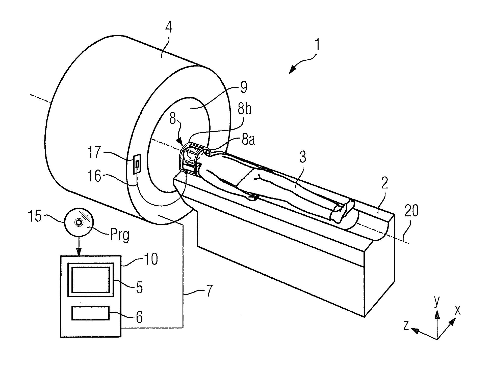
  • Figure 1
    Figure 1
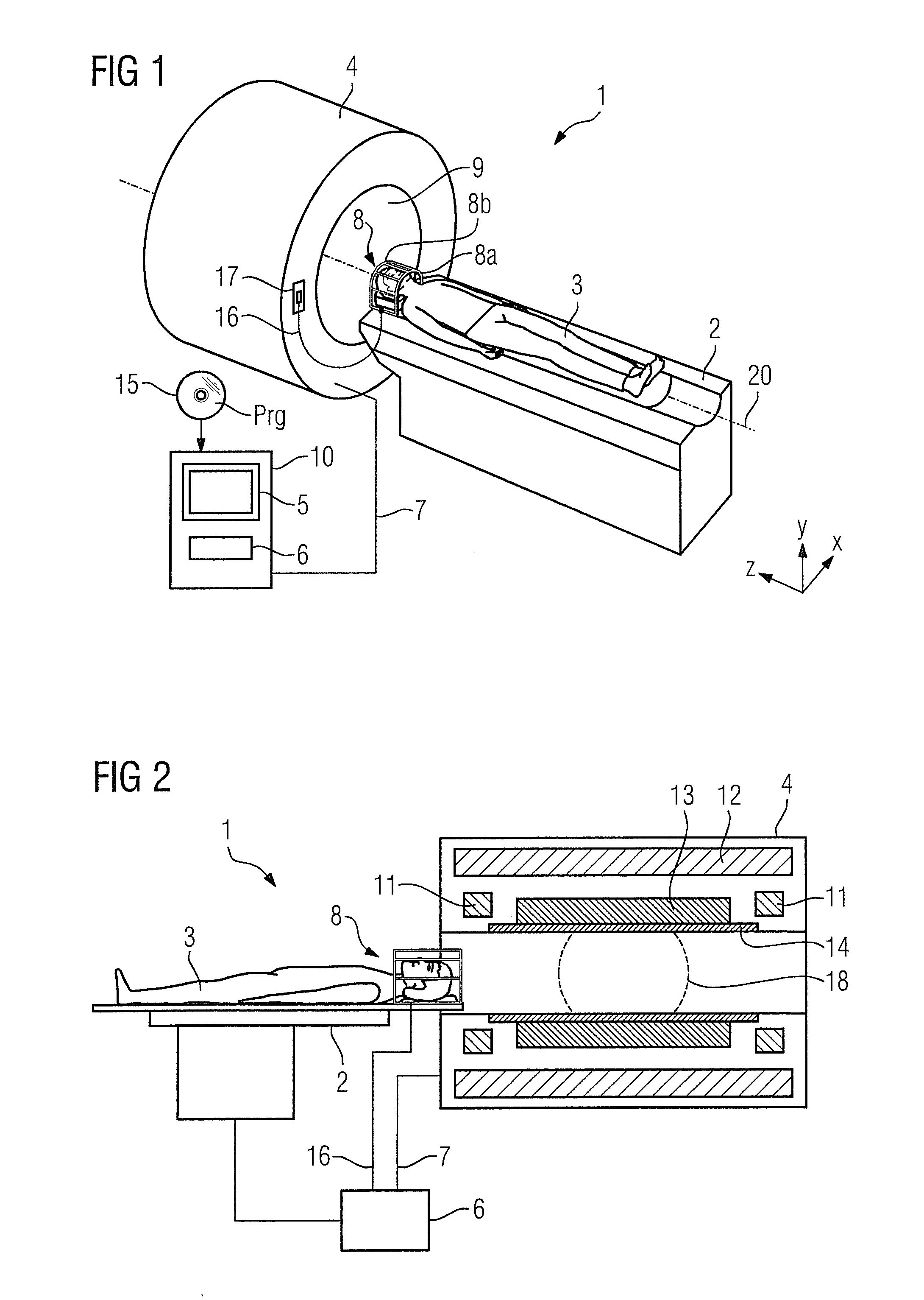
  • Figure 2
    Figure 2
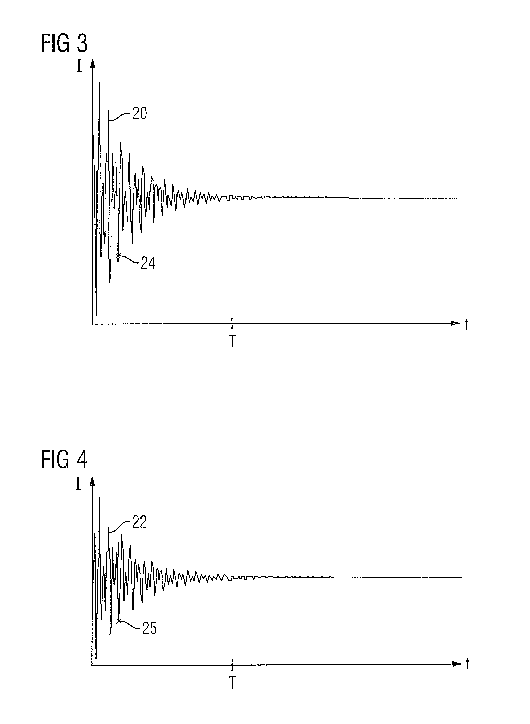
  • Figure 3
    Figure 3
Patent Text Reader

Abstract

In a method for determining a complex sensitivity factor of an RF reception coil, which is part of an arrangement of a number of RF reception coils of a magnetic resonance scanner, which are operates to simultaneously acquire magnetic resonance spectroscopy data, FID signals from a volume of interest are acquired simultaneously with each of the RF reception coils, and one of the RF reception coils is designated as a reference coil and its FID signal is designated as a reference signal. A complex sensitivity factor for each other RF reception coil is determined by minimizing the differences between a number of data points of its FID signal, weighted with the complex sensitivity factor, and the corresponding data points of the FID signal of the reference coil.
Need to check novelty before this filing date? Find Prior Art

Description

BACKGROUND OF THE INVENTION

[0001] 1. Field of the Invention

[0002] The invention relates to a method for creating a magnetic resonance spectroscopy data record for a volume of interest using a magnetic resonance unit with at least two RF reception coils, and a method for determining a complex sensitivity factor of an RF reception coil, which is part of an arrangement made up of a number of RF reception coils.

[0003] The invention also concerns a magnetic resonance apparatus, which is configured to execute the method, as well as a non-transitory, computer-readable data storage medium encoded with programming instructions for implementing such a method.

[0004] 2. Description of the Prior Art

[0005] In magnetic resonance tomography (MRT) it is frequently advantageous not to acquire the MR signal using a large radio-frequency (RF) receive coil but using an arrangement—also referred to as an array or phased array—composed of a number of RF reception coils. These can often be arranged directly on ...

Examples

Embodiment Construction

[0039]With reference to FIG. 1 an inventively embodied magnetic resonance unit 1 in the illustrated embodiment has a basic field magnet 4 with an interior space 9. A patient 3 lies on a patient bed 2, which can be moved along the device axis 20 into the interior space 9.

[0040]In the illustrated example, the head of the patient 3 is in a head coil 8, in this instance composed of two separate RF reception coils 8a and 8b, each having its own receive channel. This is only one of many conceivable exemplary embodiments. More than two RF reception coils can also be provided. The arrangement of RF reception coils can also form a body coil, for example a phased array coil. Head coils composed of four RF reception coils each arranged concentrically about an axis are also conceivable.

[0041]The head coil 8 is connected by the cable loom 16 to the connector 17 and, like all the other components of the magnetic resonance unit, is controlled by the control computer 6. This is typically integrated...