
Mounting system and a method for mounting photovoltaic modules

Active Publication Date: 2018-08-09
HANWHA Q CELLS
View PDF0 Cites 1 Cited by
  • Summary
  • Abstract
  • Description
  • Claims
  • Application Information

AI Technical Summary

Benefits of technology

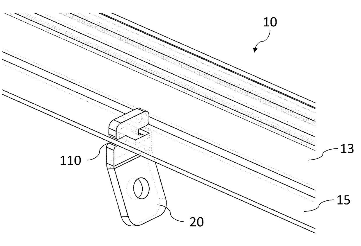
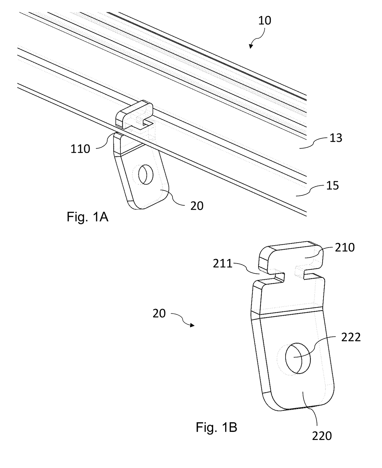
The present invention is a new and easy way to install solar power plants using numerous modules. It is particularly useful for solar power plants where the front sides of the modules are not easily accessible, and the rear sides are easier to reach. The invention allows for easy installation and de-installation by fixing the mounting elements from underneath the light incidence surface. The invention uses a steel material for all components, which prevents contact corrosion and allows for the use of thin walls or sheets. Overall, the invention simplifies the process of installing solar power plants.

Problems solved by technology

Persistent and secure connections between photovoltaic modules and a support structure that are easily to handle involve several problems which are currently not yet satisfactorily solved.
Another problem of conventional installations relates to the fact that the permanent connection is made from a front side (light incidence side) of the modules.
Since often numerous modules are to be installed in multiple rows, it becomes cumbersome to replace one of the installed modules, e.g. in an upper row, or to perform a post-processing.
Yet another problem relates to the clamps used in conventional mounting systems.
This bears the risk that those modules which do not have to be replaced, become unstable.
This may result in a flutter, particularly at windy installation sites.
In addition, it is not always possible to place the clamps directly on the mounting rails—at least as long as they are not equipped with a groove to receive a corresponding screw counterpart (for example a nut).
However, these kinds of rails are typically manufactured as extruded aluminum profile and are expensive.
Yet another problem of conventional systems relates to the requirement that the first modules in a row have to be aligned with a high precision in order to avoid that a small deviation results finally in a significant angle deviation, because such deviations grow with the number of modules installed in series along the rails.
However, the connection uses different materials and is prone to undesired contact corrosion and the suspension elements again need a clearance subject to the above-mentioned flutter.

Method used


Image

  • Mounting system and a method for mounting photovoltaic modules
  • Mounting system and a method for mounting photovoltaic modules
  • Mounting system and a method for mounting photovoltaic modules

Examples


Embodiment Construction

[0051]Various examples will now be described more fully with reference to the accompanying drawings in which some examples are illustrated.

[0052]Accordingly, while examples are capable of various modifications and alternative forms, the illustrative examples in the figures will herein be described in detail. It should be understood, however, that there is no intent to limit examples to the particular forms disclosed, but on the contrary, examples are to cover all modifications, equivalents, and alternatives falling within the scope of the disclosure. Like numbers refer to like or similar elements throughout the description of the figures.

[0053]It will be understood that when an element is referred to as being “connected” or “coupled” to another element, it can be directly connected or coupled to the other element or intervening elements may be present. In contrast, when an element is referred to as being “directly connected” or “directly coupled” to another element, there are no int...


PUM


Abstract

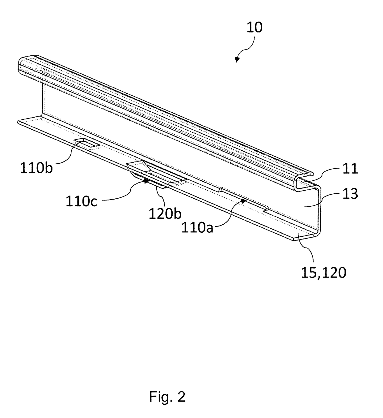
A mounting system for mounting a photovoltaic module onto at least one mounting rail. The mounting system comprises a frame for the photovoltaic module with at least one opening or protrusion at a lateral side or a bottom side of the frame, the bottom side being opposite to light incidence side of the photovoltaic module. The mounting system further comprises a plurality of mounting elements, each comprising a first portion and a second portion for securing the frame to the at least one mounting rail, the first portion defining a hook-like engagement portion to hook into the opening or the protrusion or the bottom side of the frame to provide an interlocking connection, the second portion enabling a secure fixation to the at least one mounting rail.

Description

PRIORITY CLAIM[0001]The present application claims priority to European Patent Application No. 17 155 195.5, filed on Feb. 8, 2017, which said application is incorporated by reference in its entirety herein.FIELD OF THE INVENTION[0002]The present invention relates to a mounting system and a method for mounting photovoltaic modules onto at least one mounting rail and, in particular, to a steel frame mounting concept with a click key system for mounting photovoltaic modules on rails.BACKGROUND OF THE INVENTION[0003]Persistent and secure connections between photovoltaic modules and a support structure that are easily to handle involve several problems which are currently not yet satisfactorily solved.[0004]The support structure includes typically a table-like construction with a number of rails, whereon the photovoltaic modules are to be secured. In the process of fixing the photovoltaic modules there is often a need of shifting the photovoltaic modules in all directions before a perma...

Claims


Application Information

Patent Timeline
IPC IPC(8): H02S30/10H02S30/00
CPCH02S30/10H02S30/00H02S20/00F24S25/632F24S2025/6007Y02E10/47Y02E10/50
Inventor NEUHAUSER, FRANZMOLITOR, HEIKOBUSSE, HENNINGDEWENTER, MARCEBENROTH, THOMASLINKE, THOMAS
Owner HANWHA Q CELLS
Learn More