Method of WDM channel tagging and monitoring, and apparatus

Inactive Publication Date: 2007-09-13
CIENA
View PDF3 Cites 5 Cited by
  • Summary
  • Abstract
  • Description
  • Claims
  • Application Information

AI Technical Summary

Benefits of technology

[0023] The invention enables a well known and widely implemented dithered channel tagging and monitoring technique to be applied to WDM systems that would normally be hampered by SRS. The result is a simpler, faster, less expensive and more reliable moni

Problems solved by technology

The accuracy of this method in estimating per channel power is limited by effects such as stimulated Raman scattering (SRS) which limits its usage to systems with a small number of spans, small channel counts and low per channel powers.
Modern systems are striving to achieve greater span, higher channel count and require higher channel power, thus limiting the applicability of this approach.
However, in the past, OSAs

Method used


Image

  • Method of WDM channel tagging and monitoring, and apparatus
  • Method of WDM channel tagging and monitoring, and apparatus
  • Method of WDM channel tagging and monitoring, and apparatus

Examples


Example

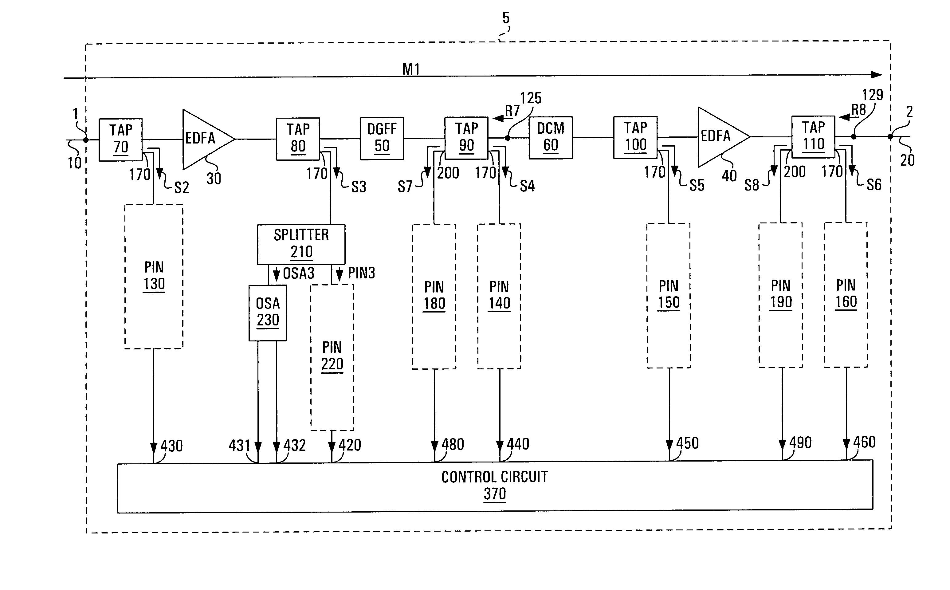
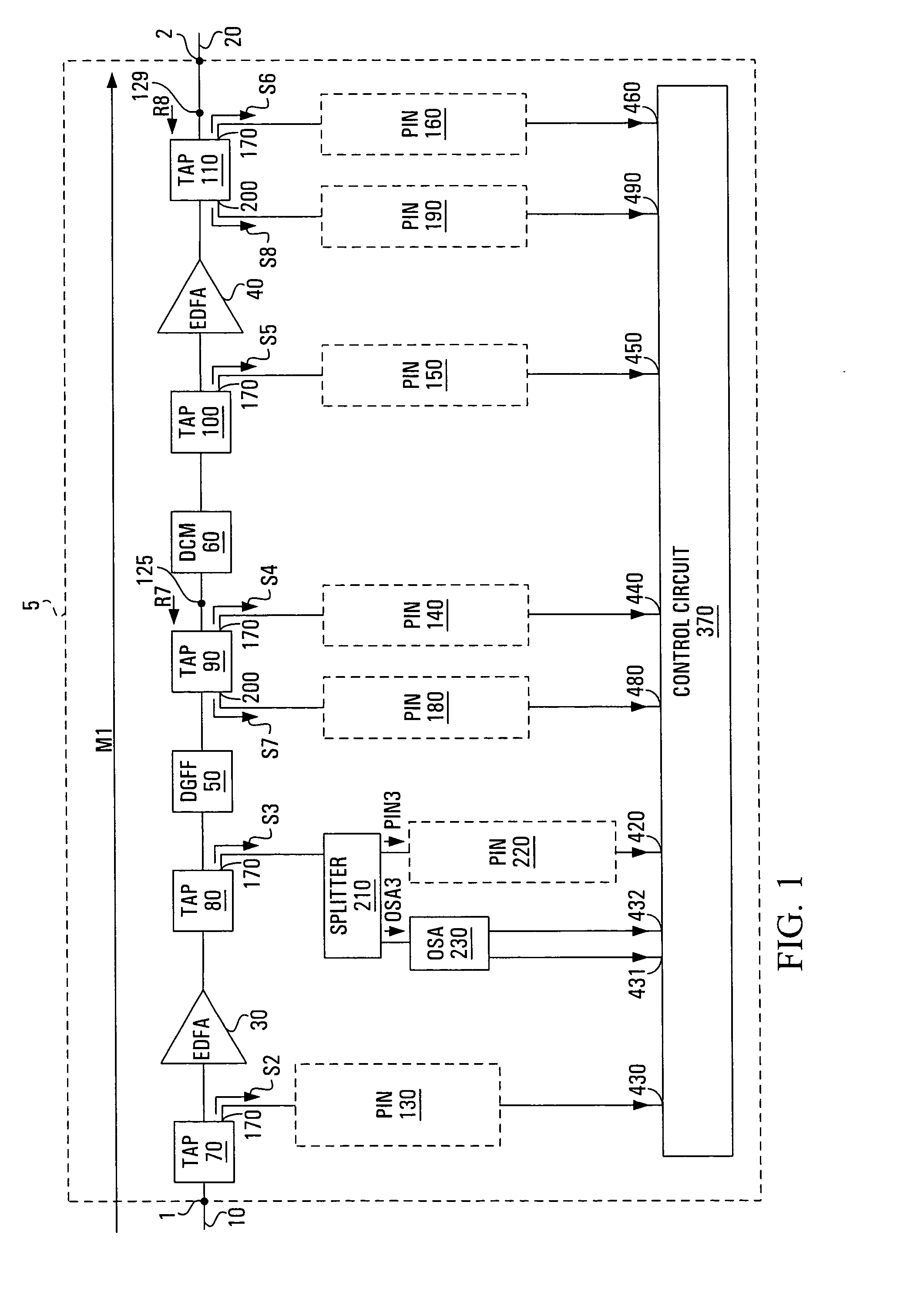
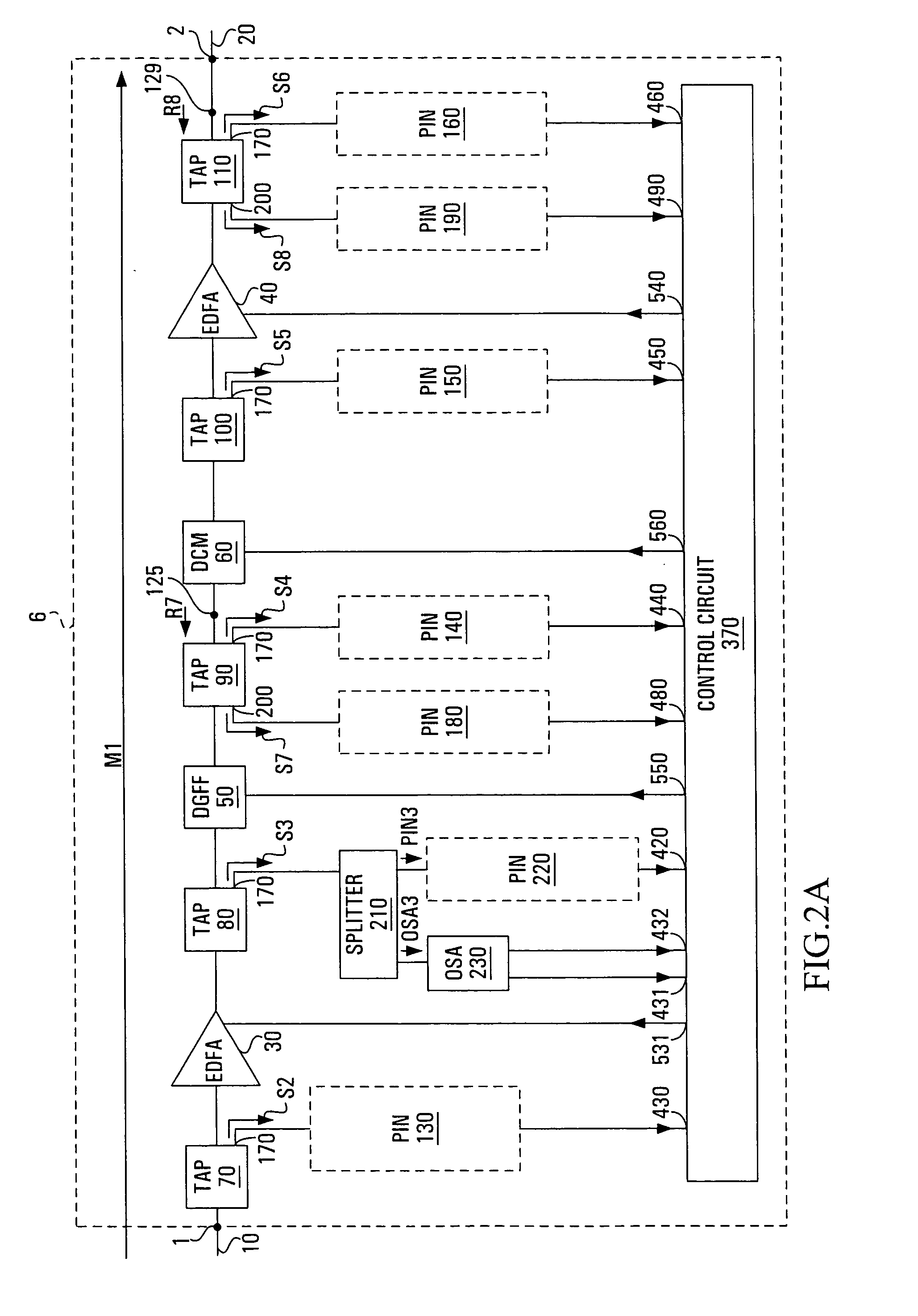
[0035] In long haul optical networks the accuracy of amplitude modulation (AM) detection or other modulation schemes using wide-band detection of an entire spectrum of channels to determine channel presence and per-channel power is limited by effects of stimulated Raman scattering (SRS). In the modulation schemes at least one channel of a multiplexed optical signal is impressed with a unique dither. In an example, for a multiplexed optical signal having N channels (carriers) each having impressed upon it a unique AM tone (a unique dither) having a fixed modulation depth and a specific frequency, cross-talk mediated by SRS or other non-linear processes results in transfer of AM tones from one channel to another. Embodiments of the invention are not limited to having all channels of the multiplexed optical signal impressed with a unique dither. In embodiments of the invention at least one of the channels is impressed with a unique dither. In an optical transmission system the power, A...


PUM


Abstract

Provided is an optical apparatus and method wherein power transfer coefficients arising from SRS are measured at a designated co-location point and the power of dithers, which are impressed on the channels of a multiplexed optical signal propagating through the optical apparatus, is measured at each co-location point. Within the optical apparatus distances between co-location points are short and the power transfer coefficients are effectively constant. Consequently, the power of each channel of the multiplexed optical signal at the co-location points is obtained from the power of the dithers at a respective one of the co-location points and the power transfer coefficients measured at the designated co-location point. In some embodiments, information on the channel power at the co-location points is used to provide instructions for compensating for fluctuations in channel power and/or channel count at an input and/or channel count within the optical apparatus.

Description

RELATED APPLICATION [0001] This application is a divisional of U.S. application Ser. No. 10 / 067,910 filed Feb. 8, 2002 and claims the benefit thereof.FIELD OF THE INVENTION [0002] The invention relates to the field of optical networks. More specifically the invention pertains to wavelength division multiplexed systems. BACKGROUND OF THE INVENTION [0003] Performance monitoring to determine channel presence and per-channel power has been employed using detection of an entire spectrum of channels of an optical signal wherein each channel has had impressed upon it a known dither. The dither can be implemented in many ways, such as amplitude modulation (AM) of a tone or set of tones or a code division multiple access (CDMA) modulation scheme, etc. [0004] In an example using AM detection each channel of a multiplexed optical signal has impressed upon it a unique AM tone and power of each channel of the optical signal is measured through differentiation of the unique AM tones and knowledge...

Claims


Application Information

Patent Timeline
IPC IPC(8): H04B10/08H04B10/02H04J14/02
CPCH04B10/07955H04J14/0227H04J14/0221
Inventor BOERTJES, DAVID W.ROBERTS, KIM B.
Owner CIENA
Why Eureka
Try Eureka