
Mapping Via Back To Back Ethernet Switches

Inactive Publication Date: 2014-12-11
MAX4G
View PDF7 Cites 4 Cited by
  • Summary
  • Abstract
  • Description
  • Claims
  • Application Information

AI Technical Summary

Benefits of technology

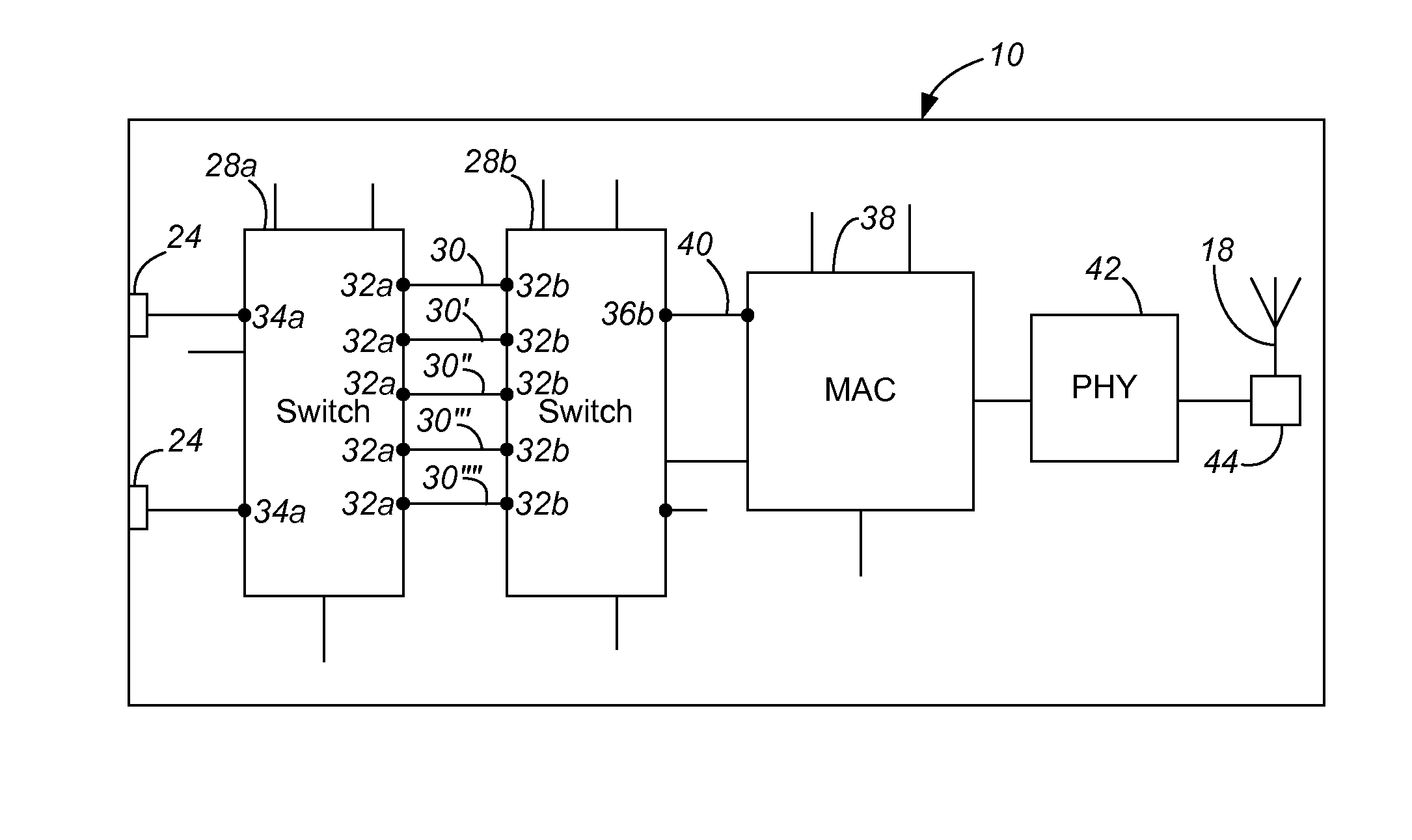
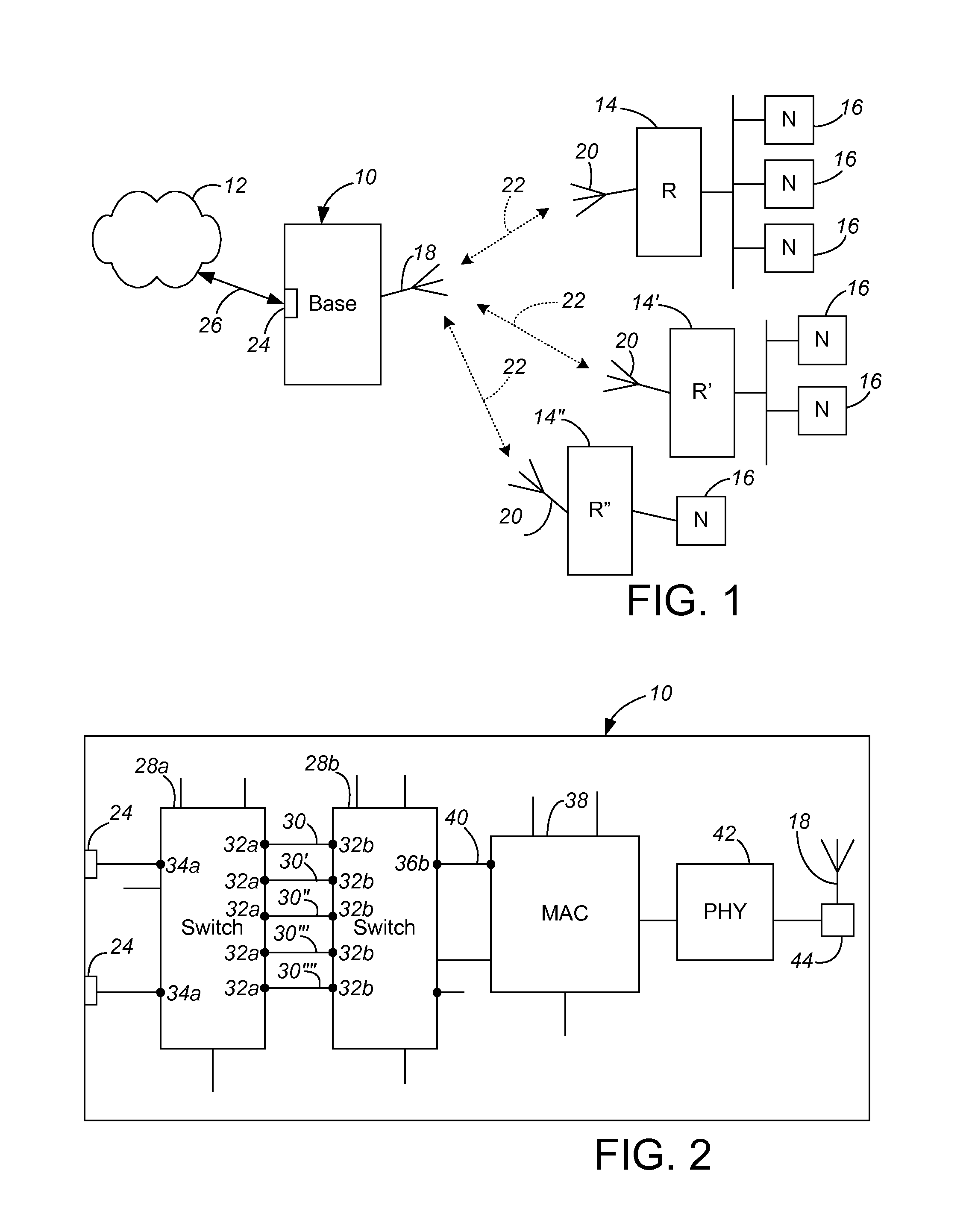
The present invention provides a simple and efficient way to switch packets in a base station. The base station has a MAC processor and two Ethernet switches. The inner Ethernet switch communicates with the MAC processor through a remote mapping tunnel that carries all data packets for connected remote stations. The inner switch also communicates with the outer switch on multiple ports. Mapping the base station-remote links' downstream packets from the MAC processor is achieved with tags added to communications through the remote mapping tunnel, such tags in the downstream direction being added in the inner Ethernet switch based upon which inter-switch port pair carried the packet.

Problems solved by technology

However, this simple approach is not optimal.
The individual base station-remote links of a deployed PtMP system are likely to be of differing quality and this quality may change over time.
This approach of managing the modulation and coding scheme for each remote unit separately, though, creates a packet switching challenge in the base station.

Method used


Image

  • Mapping Via Back To Back Ethernet Switches
  • Mapping Via Back To Back Ethernet Switches

Examples


Embodiment Construction

[0015]The present invention addresses the challenge of mapping downstream packets in the base station unit to destination remote units. The present invention proposes a solution for a PtMP wireless communication system base station unit to provide downstream packet mapping to base station-remote links using standard Ethernet switch hardware components (chips).

[0016]This disclosure uses the following terminology:

Term / AcronymDescriptionLANLocal Area Network802.1Q tagThe 32-bit addition to Ethernet headers to provide virtual LAN(VLAN) assignment.CodingTechnique used in the wireless physical layer to sendredundant information in the data stream so that errors can bedetected and possibly corrected.Data-pathThe Ethernet traffic of end-users (i.e. users of the system)travel through the PtMP data path.DownstreamThe data-path has an upstream and downstream direction forpackets to and from end-users. The downstream direction isfrom the base station unit to a remote unit.UpstreamThe data-path ...


PUM


Abstract

A base station in a fixed wireless point to multi-point communication system includes a MAC processor and inner and outer Ethernet switches. The inner Ethernet switch communicates with the outer Ethernet switch on a plurality of ports, with packets to or from each connected remote station always traveling over a single inter-switch port pair dedicated to that remote station. Mapping the base station-remote links' downstream packets from the MAC processor is achieved with tags added in the inner Ethernet switch (downstream packets, based upon which inter-switch port pair carried the packet) and in the MAC processor (upstream packets).

Description

CROSS-REFERENCE TO RELATED APPLICATION(S)[0001]The present application claims priority from Provisional Application No. 61 / 831,569, filed Jun. 5, 2013 and entitled “Wireless Point-to-Multi-Point Hub Remote Unit Mapping Using Back-to-Back Ethernet Switches”. The contents of U.S. provisional patent application Ser. No. 61 / 831,569 are hereby incorporated by reference in entirety.BACKGROUND OF THE INVENTION[0002]The present invention relates to Point-to-Multipoint (“PtMP”) wireless communication systems having one or more base stations, each of which communicates (or is capable of communicating) with multiple remote units.[0003]A PtMP system consists of a single base station unit and one or more remote units. The remote units communicate with the base station unit, and vice versa, but the remote units do not directly communicate with each other. In PtMP systems wherein the base station performs remote-to-remote forwarding, the system allows the remote units to communicate with each othe...

Claims


Application Information

Patent Timeline
IPC IPC(8): H04L12/947H04L12/931H04W88/08
CPCH04L49/25H04L49/351H04W88/08H04L49/201
Inventor KELMAN, VLADIMIR Z.KLEIN, ANTHONY J.STERN, JEFFREY T.
Owner MAX4G
Learn More