Counter Bearing for Machining Spindles of Machine Tools and Method for Clamping Counter Bearings and Tools

a technology for counter bearings and spindles, which is applied in the direction of turning machine accessories, chucks, manufacturing tools, etc., can solve the problems of contamination, inability to clean work, and inability to use high-pressure grease presses for clamping counter bearings on spindles, etc., to achieve simple and quick clamping action and reduce the pressure acting on the pressure medium

Active Publication Date: 2018-11-22
MICHAEL WEINIG AG
View PDF1 Cites 3 Cited by
  • Summary
  • Abstract
  • Description
  • Claims
  • Application Information

AI Technical Summary

Benefits of technology

[0005]The counter bearing according to the invention is characterized by a closed system for the clamping action. In order to pressurize the pressure medium for the clamping process, the pressure element is mechanically actuated by means of a tool so that a piston is displaced in the direction toward the pressure chamber and causes the pressure medium contained therein to be pressurized. In this way, a simple and quick clamping action without use of a gr...

Problems solved by technology

Clean working is not possible with such a clamping device.
The grease reaches the exterior and causes a contamination not only during the clamping p...

Method used


Image

  • Counter Bearing for Machining Spindles of Machine Tools and Method for Clamping Counter Bearings and Tools
  • Counter Bearing for Machining Spindles of Machine Tools and Method for Clamping Counter Bearings and Tools
  • Counter Bearing for Machining Spindles of Machine Tools and Method for Clamping Counter Bearings and Tools

Examples


Embodiment Construction

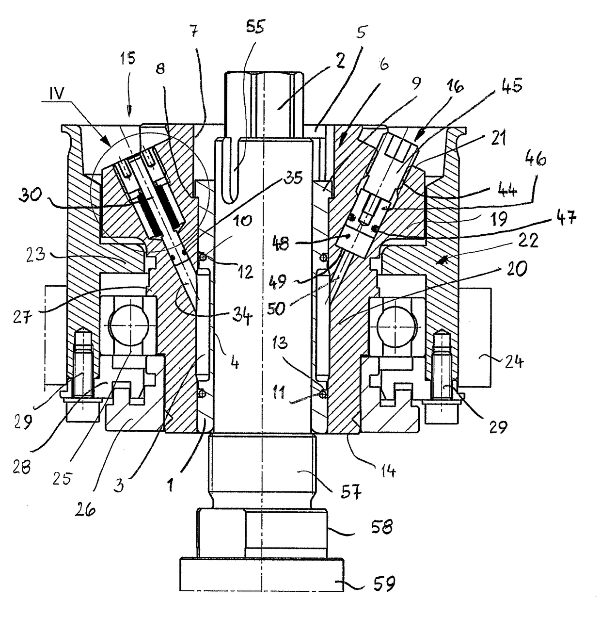
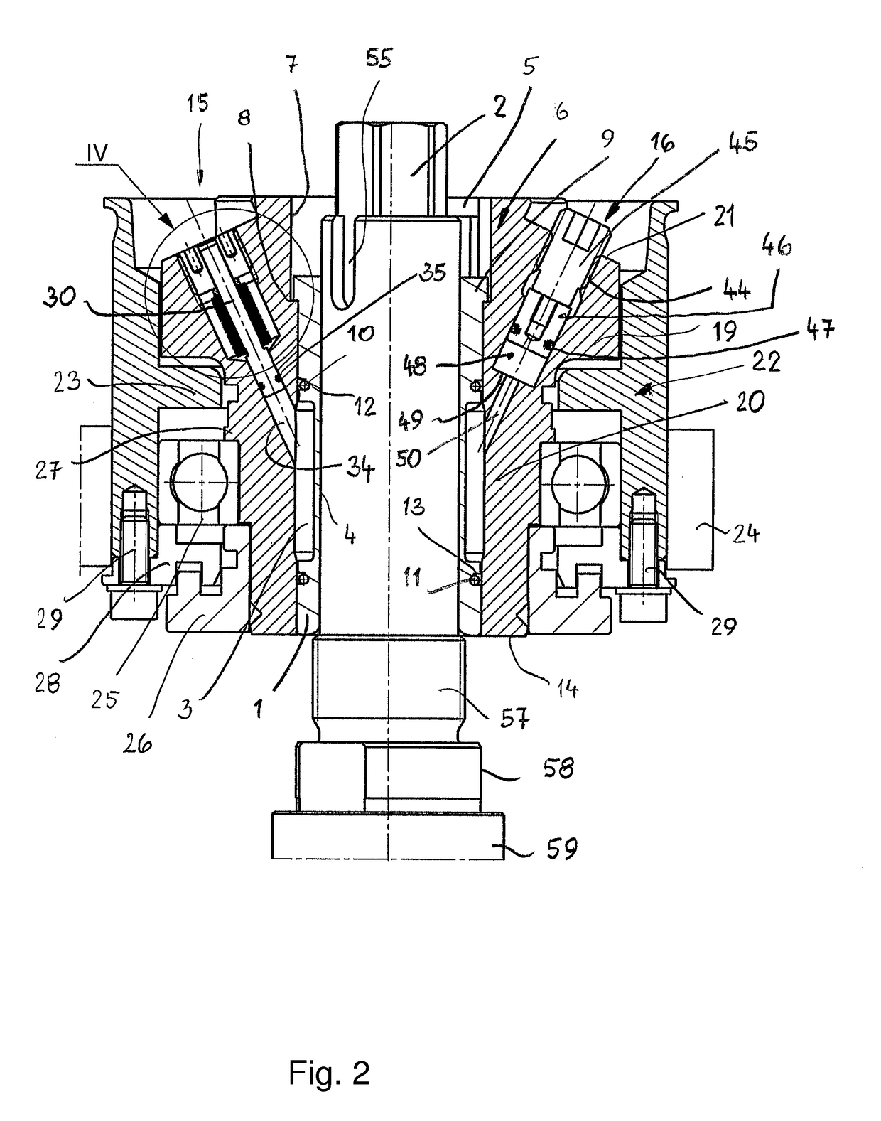
[0029]The clamping device in the illustrated embodiment is part of a counter bearing that enables a play-free and centered connection with the spindle. It comprises a hydraulic expansion bushing 1 (FIG. 2) that surrounds a spindle pin 2. The hydraulic expansion bushing 1 is provided with a pressure chamber 3 which extends across a portion of the length and about the circumference of the hydraulic expansion bushing 1. In radial direction inwardly, the pressure chamber 3 is delimited by a thin-walled region 4 of the hydraulic expansion bushing 1 which, under the pressure of a pressure medium located in the pressure chamber, can be elastically deformed in radial direction inwardly in order to clamp the spindle pin.

[0030]The hydraulic expansion bushing 1 is housed in a through opening 5 of a bearing hub 6. The through opening 5 is delimited by a wall 7 which is provided with an annular shoulder 8 at which the hydraulic expansion bushing 1 is supported in an axial direction. For this pur...


PUM

PropertyMeasurementUnit
Pressureaaaaaaaaaa

Abstract

A counter bearing for machining spindles of machine tools has at least one expansion bushing with an elastically deformable wall that delimits at least one pressure chamber. The pressure chamber accommodates a pressure medium. A supply line for the pressure medium opens into the pressure chamber. A pressure conduit opens into the pressure chamber. A mechanically actuatable pressure element is disposed in the pressure conduit and actuated by an actuating tool. A piston is slidably arranged in the pressure conduit and actuated by the pressure element, wherein the piston loads the pressure medium.

Description

BACKGROUND OF THE INVENTION[0001]The invention relates to a counter bearing for machining spindles of machine tools according to the preamble of claim 1 as well as a method for clamping counter bearings and tools on machining spindles of machine tools according to the preamble of claim 14.[0002]For clamping counter bearings of spindles, clamping devices are known which are provided with expansion bushings. They each comprise an elastically deformable wall that delimits an annular pressure chamber. A pressure medium, preferably grease, is introduced with pressure into the pressure chambers. When the counter bearing is to be clamped on the spindle, a high-pressure grease press is connected to a corresponding connector with which the grease is pumped at high pressure into the pressure chamber. For releasing the clamping action, a valve is opened through which a portion of the grease is discharged. Clean working is not possible with such a clamping device. The grease reaches the exterio...

Claims


Application Information

Patent Timeline
IPC IPC(8): B23B31/26
CPCB23B31/261B23B2260/026B23B2260/008B23B31/302B23B31/305B23B2231/26B23B2260/088B23B2260/142B23B2270/483
Inventor WAGNER, RALFGRAMLICH, RAINER
Owner MICHAEL WEINIG AG
Why Eureka
Try Eureka