

Polymer prosthesis
- Summary
- Abstract
- Description
- Claims
- Application Information
AI Technical Summary
Benefits of technology
Problems solved by technology
Method used
Image

Examples
third embodiment
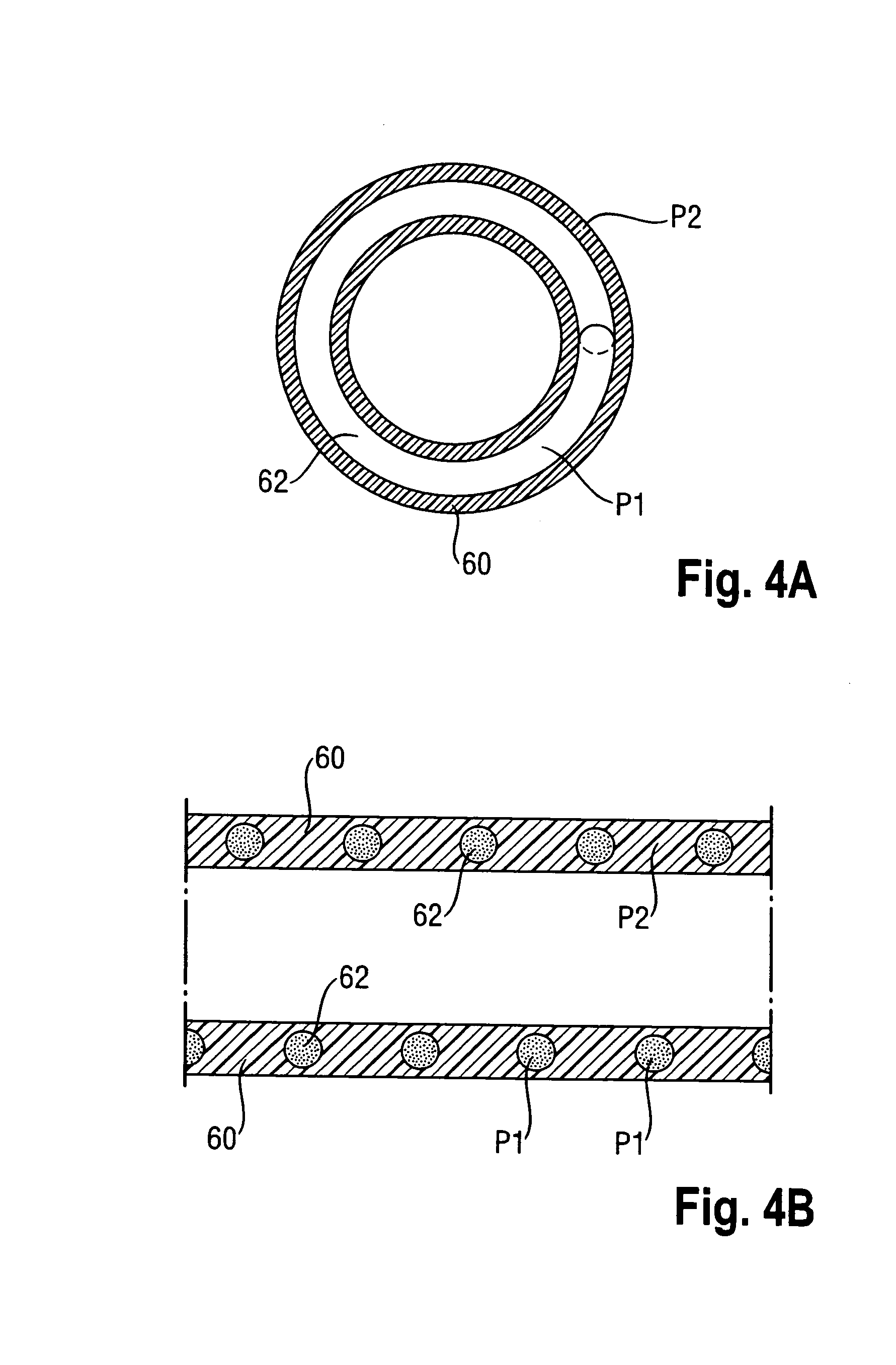
[0061]FIG. 4A-8B show schematically cross-sections of embodiments of a polymer prosthesis in accordance with the present invention. More in particular, FIG. 4A and FIG. 4B each show cross-sections of a third embodiment, wherein the polymer P1 of the relatively stiff stenting segments 62, is encapsulated between two layers of polymer P2 of the relatively flexible linking segments 60, which are in a form of two concentric layers of ePTFE.
fourth embodiment
[0062]FIGS. 5A and 5B each show cross-sections of a fourth embodiment, wherein the polymer P1 of the relatively stiff stenting segments 62 is positioned radially outwardly from the cylindrical component 60, acting here as the plurality of relatively flexible linking segment as portions of the continuous cylindrical component 60, which is preferably of ePTFE.
fifth embodiment
[0063]FIG. 6A and FIG. 6B each show cross-sections of a fifth embodiment similar to the embodiment shown in FIGS. 5A and 5B. However, in FIGS. 6A and 6B the polymer P1 of the relatively stiff stenting segments is positioned at least partly within interstices formed in the polymer P2 of the plurality of relatively flexible linking segments, here again shown in the form of a continuous cylindrical component 60, preferably made of ePTFE.
PUM
 Abstract
Description
Claims
Application Information