Redundant control method for a polyphase converter with distributed energy stores

Active Publication Date: 2013-09-17
SIEMENS AG
View PDF11 Cites 1 Cited by
  • Summary
  • Abstract
  • Description
  • Claims
  • Application Information

AI Technical Summary

Benefits of technology

The patent text describes two methods for improving the performance of power converters that have faulty subsystems. In the first method, the remaining subsystems are connected to an energy source for a short time to recharge their energy stores. Once the energy store reaches a predetermined level, the subsystem is disconnected. This process increases the overall voltage of the converter without needing to add any new hardware. In the second method, an additional valve arm current is set to further increase the capacitor voltage of the remaining subsystems. These methods improve the efficiency and reliability of power converters with faulty subsystems.

Problems solved by technology

An unbalanced voltage system is formed from a balanced three-phase voltage system, which is present at the output terminals of the converter with distributed energy stores, as a result of the failure of at least one subsystem in one valve arm of one phase module.

Method used


Image

  • Redundant control method for a polyphase converter with distributed energy stores
  • Redundant control method for a polyphase converter with distributed energy stores
  • Redundant control method for a polyphase converter with distributed energy stores

Examples


Embodiment Construction

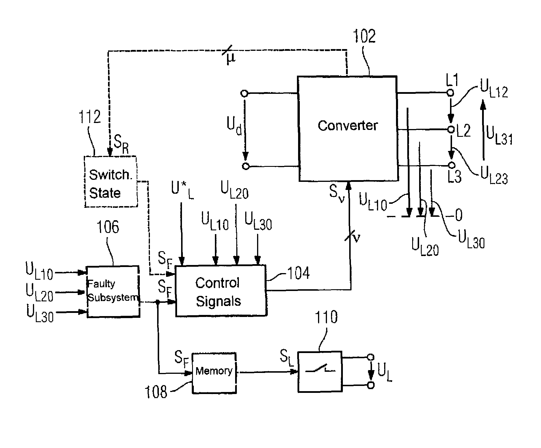
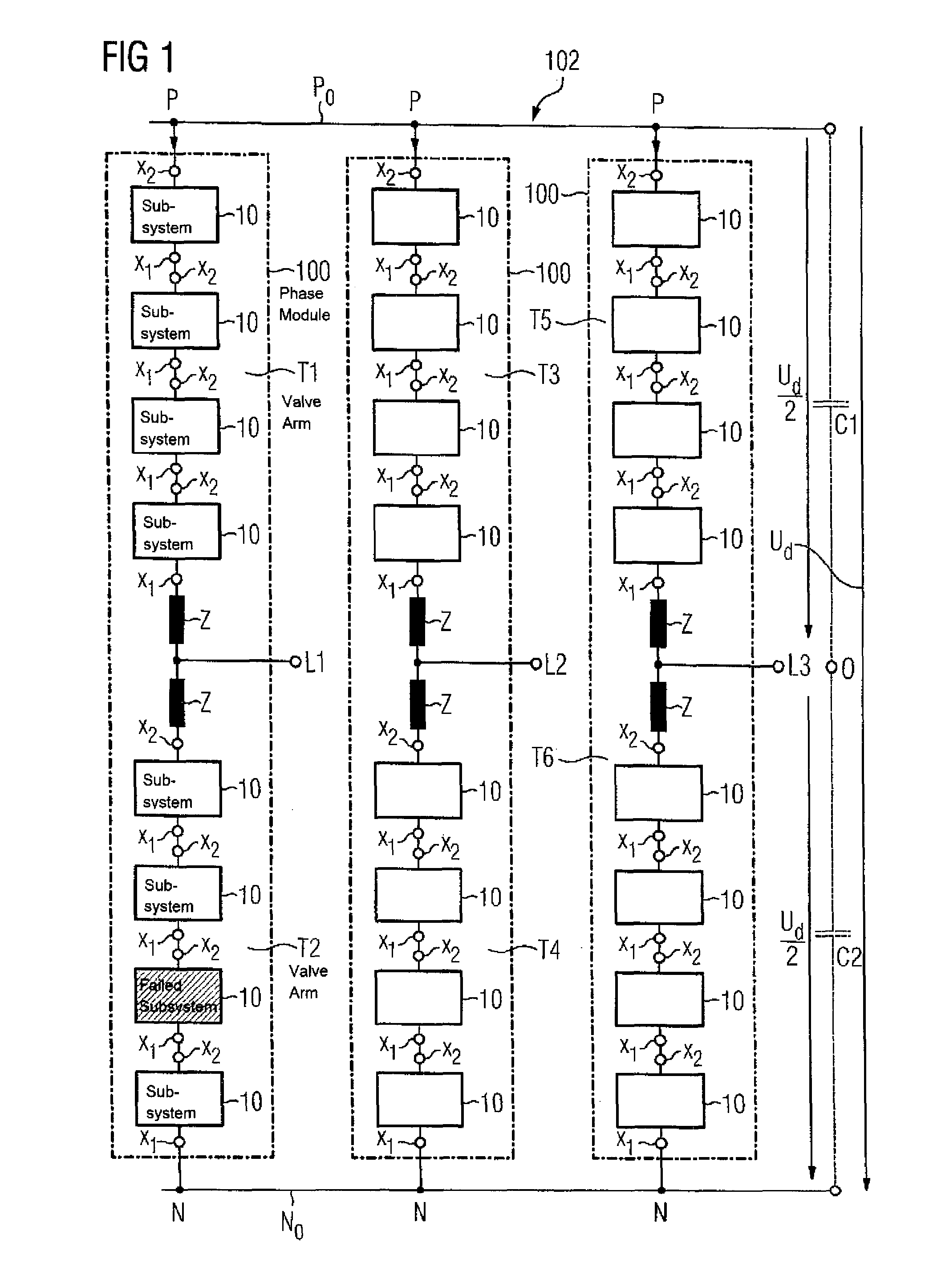
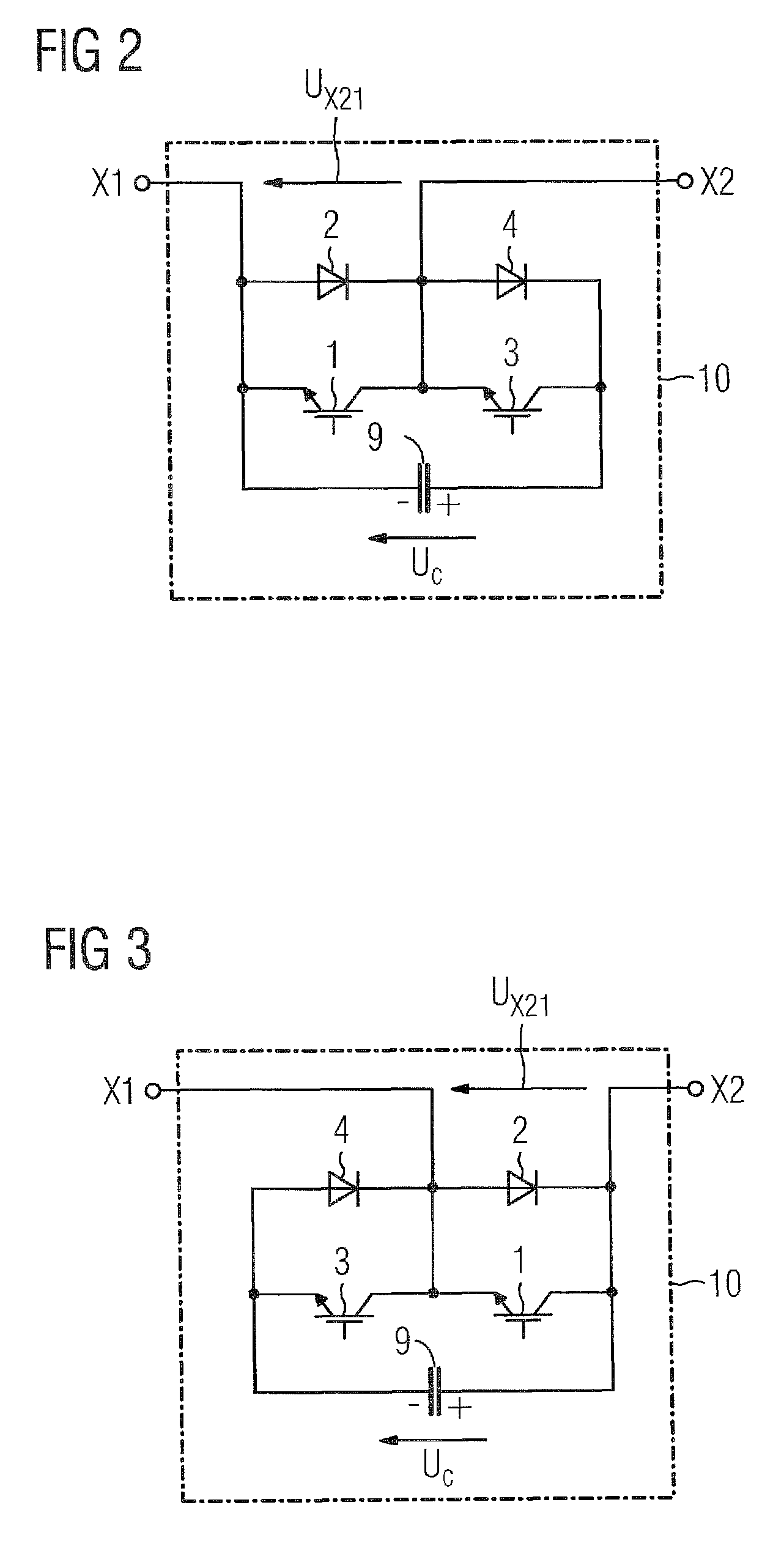
[0036]FIG. 12 shows a block diagram of a control system for a converter 102 with distributed energy stores 9 as shown in FIG. 1. In this block diagram, 104 denotes a device for production of control signals Sv, 106 denotes a device for determination of faulty subsystems 10, 108 denotes a memory apparatus and 110 denotes a low-voltage energy source which can be connected. On the output side, the device 104 is electrically conductively connected to control connections of the semiconductor switches 1 and 3 in the two-pole subsystems 10 in the valve arms T1 to T6 in the converter 102. The output voltages UL10, UL20 and UL30 which are present at the connections L1, L2 and L3 on the AC voltage side, also referred to as the output terminals of the converter 102, are supplied to the device 106 for determination of faulty two-pole subsystems 10. On the output side, this device 106 is linked on the one hand to an input of the device 104 for production of control signals Sv, and on the other h...


PUM


Abstract

An inverter having three phase modules with an upper valve arm and a lower valve arm having each at least three two-pole subsystems connected in series, which each subsystem having a storage capacitor, is controlled in the event of failure of one or more subsystems by setting the terminal voltage of the failed subsystems permanently to zero, setting the terminal voltage of a corresponding number of fault-free subsystems in corresponding fault-free valve branches likewise to zero, and increasing the capacitor voltages of the fault-free subsystems of the failed valve branches such that their sum is equal to the sum of the capacitor voltages of the subsystems of a corresponding fault-free valve branch, while leaving the control of the fault-free phase modules unchanged. In this way, a symmetrical voltage system with maximum amplitude is obtained at the inverter outputs.

Description

CROSS-REFERENCES TO RELATED APPLICATIONS[0001]This application is the U.S. National Stage of International Application No. PCT / EP2009 / 055808, filed May 14, 2009, which designated the United States and has been published as International Publication No. WO 2010 / 015430 and which claims the priority of German Patent Application, Serial No. 10 2008 036 811.3, filed Aug. 7, 2008, pursuant to 35 U.S.C. 119(a)-(d).BACKGROUND OF THE INVENTION[0002]The invention relates to a method for controlling a converter with distributed energy stores.[0003]DE 101 03 031 A1 discloses a converter with distributed energy stores. An equivalent circuit of a converter such as this is shown in more detail in FIG. 1. According to this equivalent circuit, this known converter, which is annotated 102, has three phase modules, which are each annotated 100. These phase modules 100 are each electrically conductively connected on the DC voltage side to a positive and a negative DC voltage busbar P0 and N0. In the ca...

Claims


Application Information

Patent Timeline
IPC IPC(8): H02H7/122
CPCH02M7/49H02M2007/4835H02M7/4835
Inventor HILLER, MARCKRUG, DIETMAR
Owner SIEMENS AG
Why Eureka
Try Eureka