Membrane carburetor

a carburetor and membrane technology, applied in the direction of liquid fuel feeders, machines/engines, separation processes, etc., can solve the problems of increased exhaust-gas values, inability to run internal combustion engines,

Active Publication Date: 2007-08-09
ANDREAS STIHL AG & CO KG
View PDF13 Cites 2 Cited by
  • Summary
  • Abstract
  • Description
  • Claims
  • Application Information

AI Technical Summary

Benefits of technology

[0015]The inlet valve has a control body which is fixedly connected to the valve body of the inlet valve. Advantageously, the control body is configured as an actuating piston which delimits a pressure chamber into which the pressure line opens. With the configuration of the control body itself as an actuating piston, no additional components are needed. The control body can also be configured as one piece with the valve body of the inlet valve. The control body is especially configured as a weight body. The weight body can provide a position compensation of the membrane carburetor.

Problems solved by technology

In this way, air bubbles can collect in the pump chamber during longer operating times. If these air bubbles are moved into the intake channel during a later acceleration operation, then instability in the running performance of the internal combustion engine and increased exhaust-gas values occur.

Method used


Image

  • Membrane carburetor
  • Membrane carburetor
  • Membrane carburetor

Examples


Embodiment Construction

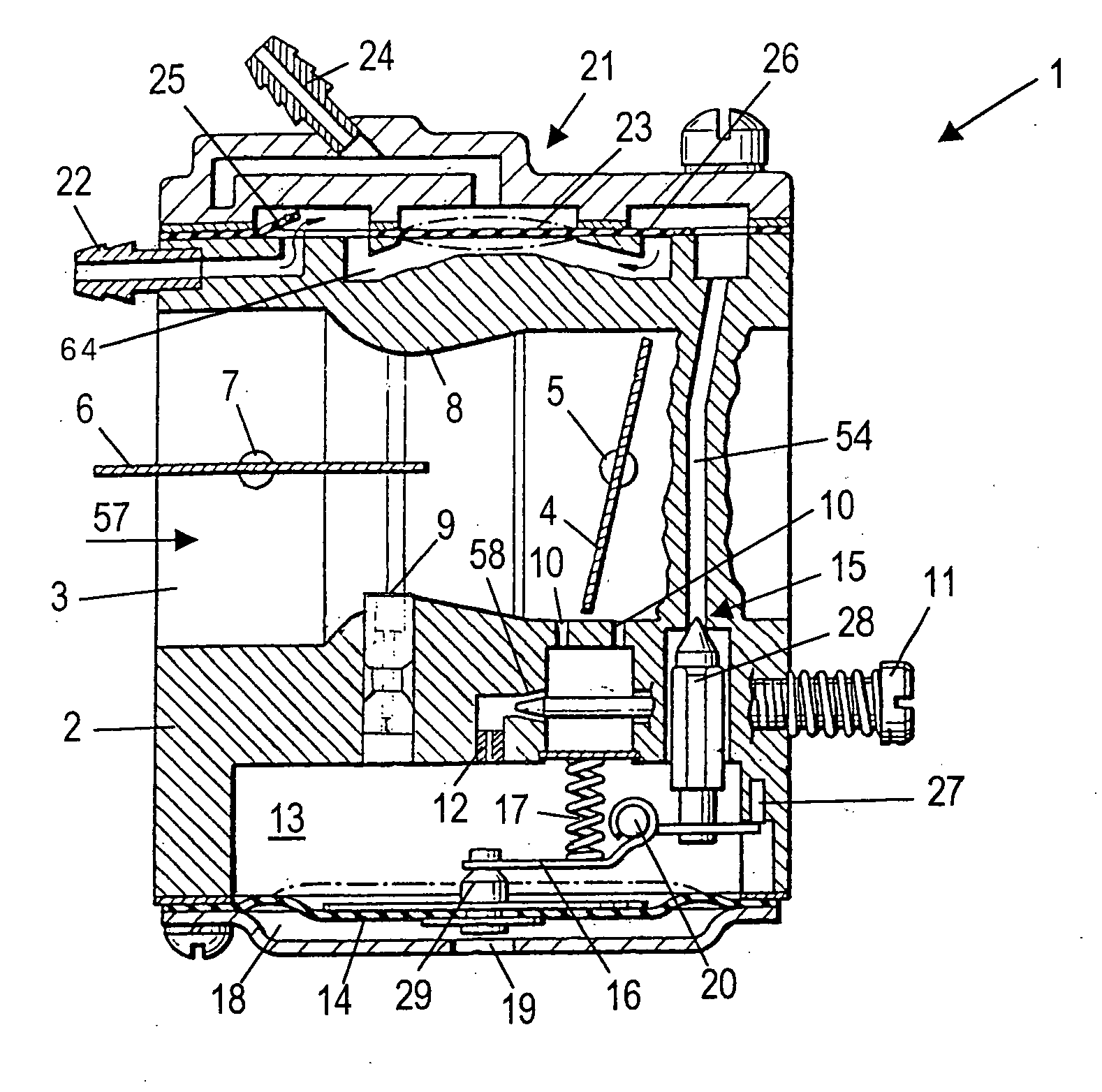
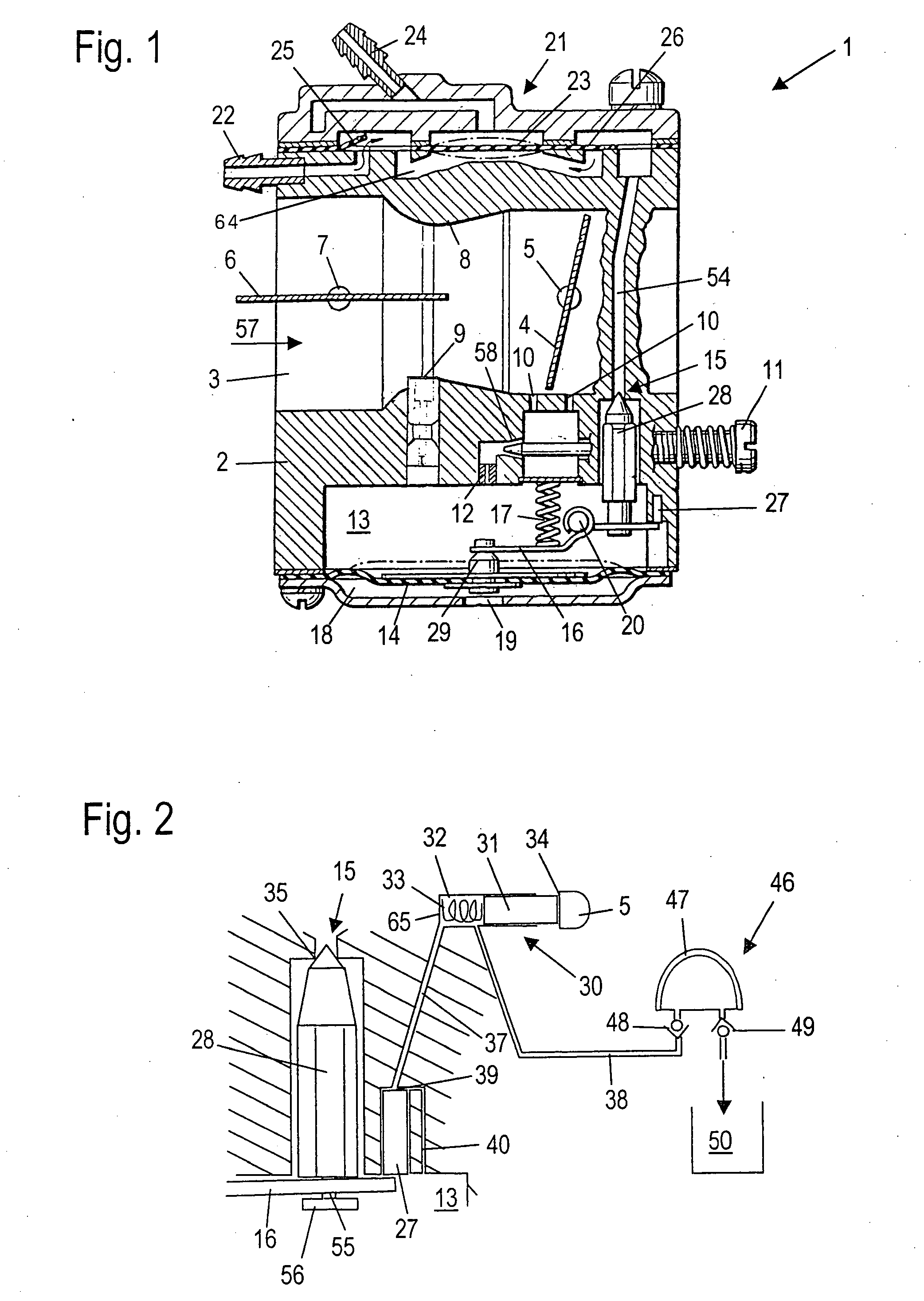
[0022]The membrane carburetor 1 shown in FIG. 1 has a carburetor housing 2 through which a section of an intake channel 3 is extended. The intake channel 3 leads to an internal combustion engine. The internal combustion engine is especially the drive motor of a work tool in a portable handheld work apparatus such as a motor-driven chain saw, cutoff machine, brushcutter or the like. In the carburetor housing 2, a throttle flap 4 having a throttle shaft 5 is pivotally journalled in the intake channel 3. In lieu of the throttle flap 4, another throttle element can be mounted in the intake channel 3.

[0023]Referred to the flow direction 57, a choke flap 6 having a choke shaft 7 is pivotally journalled in the intake channel 3 upstream of the throttle flap 4. A venturi 8 is formed in the intake channel 3 between the choke flap 6 and the throttle flap 4 in the flow direction 57. In this region, a main fuel opening 9 opens into the intake channel. Downstream of the main fuel opening 9, ancil...


PUM

PropertyMeasurementUnit
weight ratiosaaaaaaaaaa
pressureaaaaaaaaaa
accelerationaaaaaaaaaa

Abstract

A membrane carburetor (1) has a control chamber (13) which is connected via at least one fuel opening (9, 10) to an intake channel (3). The control chamber (13) is delimited by a control membrane (14). A fuel line (54) opens into the control chamber (13) via an inlet valve (15). The inlet valve (15) opens in dependence upon the deflection of the control membrane (14). The membrane carburetor (1) has an acceleration pump (30) which is actuated in dependence upon the position of a throttle element held in the intake channel (3). A good acceleration enrichment and a stable running of the internal combustion engine are achieved when the acceleration pump (30) operates hydraulically on at least one actuating member in the control chamber (13).

Description

CROSS REFERENCE TO RELATED APPLICATION[0001]This application claims priority of German patent application no. 10 2006 005 696.5, filed Feb. 8, 2006, the entire content of which is incorporated herein by reference.FIELD OF THE INVENTION[0002]The invention relates to a membrane carburetor including a membrane carburetor for a portable handheld work apparatus such as a motor-driven chain saw, brushcutter or the like.BACKGROUND OF THE INVENTION[0003]U.S. Pat. No. 5,250,233 discloses a membrane carburetor having a control chamber delimited by a control membrane and an acceleration pump actuated by a throttle shaft. The acceleration pump includes a pump chamber which is connected via a line to the control chamber. The line opens into the control chamber in the region of fuel openings opening into the intake channel.[0004]The pump chamber of the acceleration pump defines a dead space wherein fuel is drawn in by suction only at pregiven operating conditions or fuel is pumped out. During con...

Claims


Application Information

Patent Timeline
Patent Type & Authority Applications(United States)
IPC IPC(8): F02M69/02
CPCF02M17/04F02M7/08
Inventor PRAGER, ANDRE
Owner ANDREAS STIHL AG & CO KG
Why Eureka
Try Eureka