Controller for extending a protection period of a power converter and operational method thereof

Active Publication Date: 2019-12-19
LEADTREND TECH
View PDF3 Cites 2 Cited by
  • Summary
  • Abstract
  • Description
  • Claims
  • Application Information

AI Technical Summary

Benefits of technology

The present invention is a controller and method for extending the protection period of a power converter. It uses a delay circuit to extend the protection period based on the supply voltage after the power converter enters the protection mode. This helps to effectively dissipate heat generated by the power switch during the recovery period, which can improve the overall performance of the power converter. The controller also controls the supply voltage directly, eliminating the need for an additional pin.

Problems solved by technology

If during a disabling time of the gate control signal (corresponding to a protection period of the protection mode), the heat generated by the power switch during the recovery period cannot be effectively dissipated, the heat generated by the power switch during the recovery period may damage components within the television.
Therefore, how to effectively dissipate the heat generated by the power switch during the recovery period becomes an important issue.

Method used


Image

  • Controller for extending a protection period of a power converter and operational method thereof
  • Controller for extending a protection period of a power converter and operational method thereof
  • Controller for extending a protection period of a power converter and operational method thereof

Examples


first embodiment

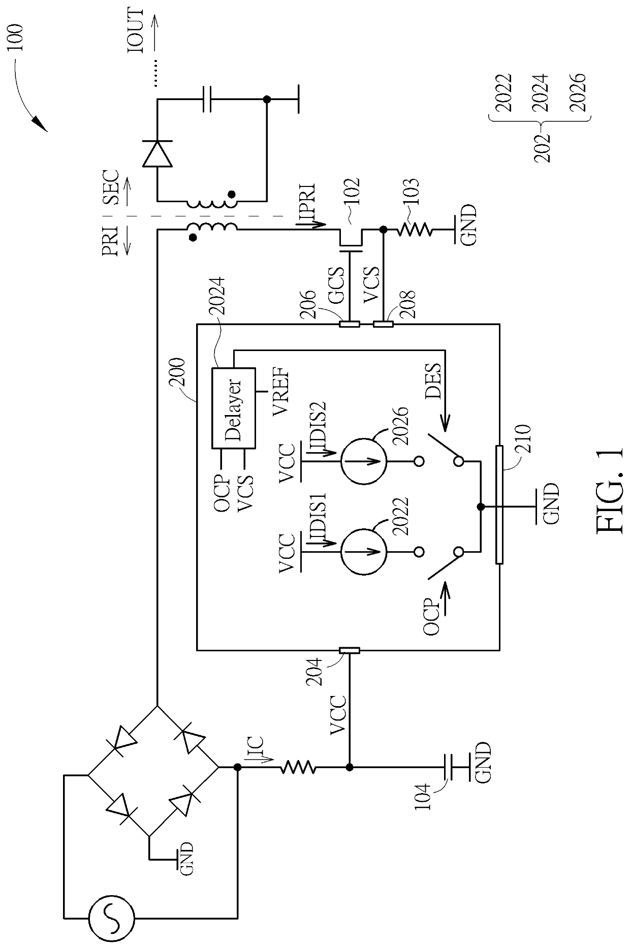
[0017]Please refer to FIG. 1. FIG. 1 is a diagram illustrating a controller 200 for extending a protection period of a power converter 100 according to the present invention, wherein the power converter 100 is a flyback power converter, and FIG. 1 only shows components of the power converter 100 and the controller 200 related to the present invention to simplify FIG. 1. As shown in FIG. 1, the controller 200 includes a delay circuit 202, and the delay circuit 202 includes a first current source 2022, a delayer 2024, and a second current source 2026, wherein the first current source 2022 is coupled to a supply voltage pin 204, the second current source 2026 is coupled to the delayer 2024 and the supply voltage pin 204, and the controller 200 receives a supply voltage VCC through the supply voltage pin 204. As shown in FIG. 1, a protection circuit (not shown in the controller 200 of FIG. 1) of the controller 200 can determine whether to make the power converter 100 enter a protection ...

second embodiment

[0022]Please refer to FIGS. 5, 6. FIG. 5 is a diagram illustrating a controller 500 for extending the protection period of the power converter 100 according to the present invention, and FIG. 6 is a timing diagram illustrating a supply voltage VCC of the controller 500 and a gate control signal GCS generated by the controller 500 after the power converter 100 enters the protection mode, wherein FIG. 5 only shows components of the power converter 100 and the controller 500 related to the present invention to simplify FIG. 5. As shown in FIG. 5, differences between the controller 500 and the controller200 are that the controller 500 includes a delay circuit 502, and the delay circuit 502 includes a current source 5022 and a counter 5024, wherein the current source 5022 is coupled to the supply voltage pin 204, the counter 5024 is coupled to the current source 5022, and the controller 500 receives the supply voltage VCC through the supply voltage pin 204. In addition, as shown in FIG. ...

third embodiment

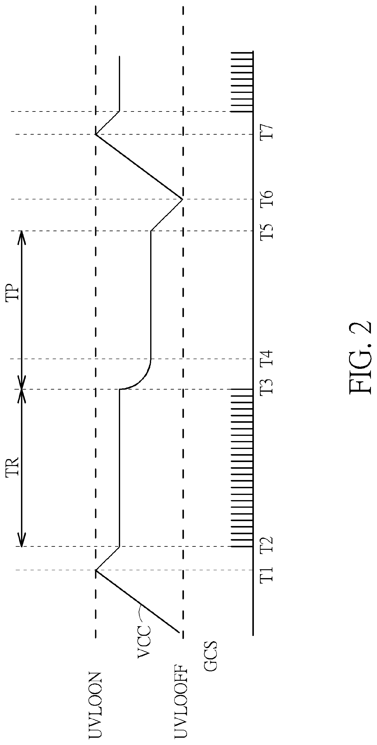
[0024]Please refer to FIGS. 1, 2, 7. FIG. 7 is a flowchart illustrating an operational method of a controller extending a protection period of a power converter according to the present invention. The operational method in FIG. 7 is illustrated using the power converter 100 and the controller 200 in FIG. 1. Detailed steps are as follows:

[0025]Step 700: Start.

[0026]Step 702: The power converter 100 enters the protection mode.

[0027]Step 704: The first current source 2022 generates the first discharge current IDIS1 according to the protection signal OCP and the supply voltage VCC.

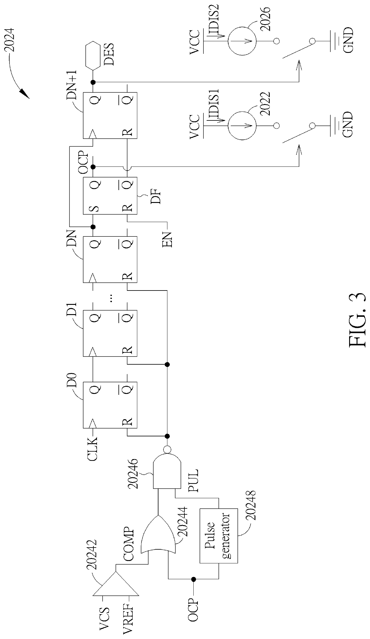
[0028]Step 706: The delayer 2024 generates the delay enabling signal DES according to the protection signal OCP and the detection voltage VCS.

[0029]Step 708: The second current source 2026 generates the second discharge current IDIS2 according to the delay enabling signal DES.

[0030]Step 710: When the supply voltage VCC is lower than the under voltage lock out turning-off voltage UVLOOFF, the controller 200 dis...


PUM


Abstract

A controller for extending a protection period of a power converter includes a delay circuit. The delay circuit is coupled to a supply voltage pin of the controller. When the power converter enters a protection mode, the delay circuit is enabled, receives a supply voltage through the supply voltage pin, and extends a protection period corresponding to the protection mode according to the supply voltage.

Description

CROSS REFERENCE TO RELATED APPLICATIONS[0001]This application claims the benefit of U.S. Provisional Application No. 62 / 686,691, filed on Jun. 19, 2018 and entitled “Novel IC protection pause status in Flyback Controller,” the contents of which are incorporated herein by reference.BACKGROUND OF THE INVENTION1. Field of the Invention[0002]The present invention relates to a controller applied to a power converter and an operational method thereof, and particularly to a controller and an operational method thereof that can extend a protection period of the power converter.2. Description of the Prior Art[0003]In the prior art, when a power converter is applied to a television and enters a protection mode (wherein the protection mode corresponds to output short-circuited protection (OSCP) or over current protection (OCP)), because the television cannot be turned off arbitrarily, a gate signal generation circuit of a controller applied to the power converter can generate a gate control si...

Claims


Application Information

Patent Timeline
IPC IPC(8): H02M1/32H02M3/335
CPCH02M2001/322H02M1/32H02M3/33576H02M2001/0009H02M1/36H02M3/33507H02M1/0009H02M1/322
Inventor TSOU, MING-CHANGYEH, CHIH-PULU, RU-HUNG
Owner LEADTREND TECH
Why Eureka
Try Eureka