
Fuel cell and a temperature control system for the fuel cell

Inactive Publication Date: 2005-01-06
HONDA MOTOR CO LTD
View PDF0 Cites 10 Cited by
  • Summary
  • Abstract
  • Description
  • Claims
  • Application Information

AI Technical Summary

Benefits of technology

[0015] According to the present invention, a second aspect of the present invention provides a fuel cell with the improvement in decrease in efficiency of a pump at a low temperature.
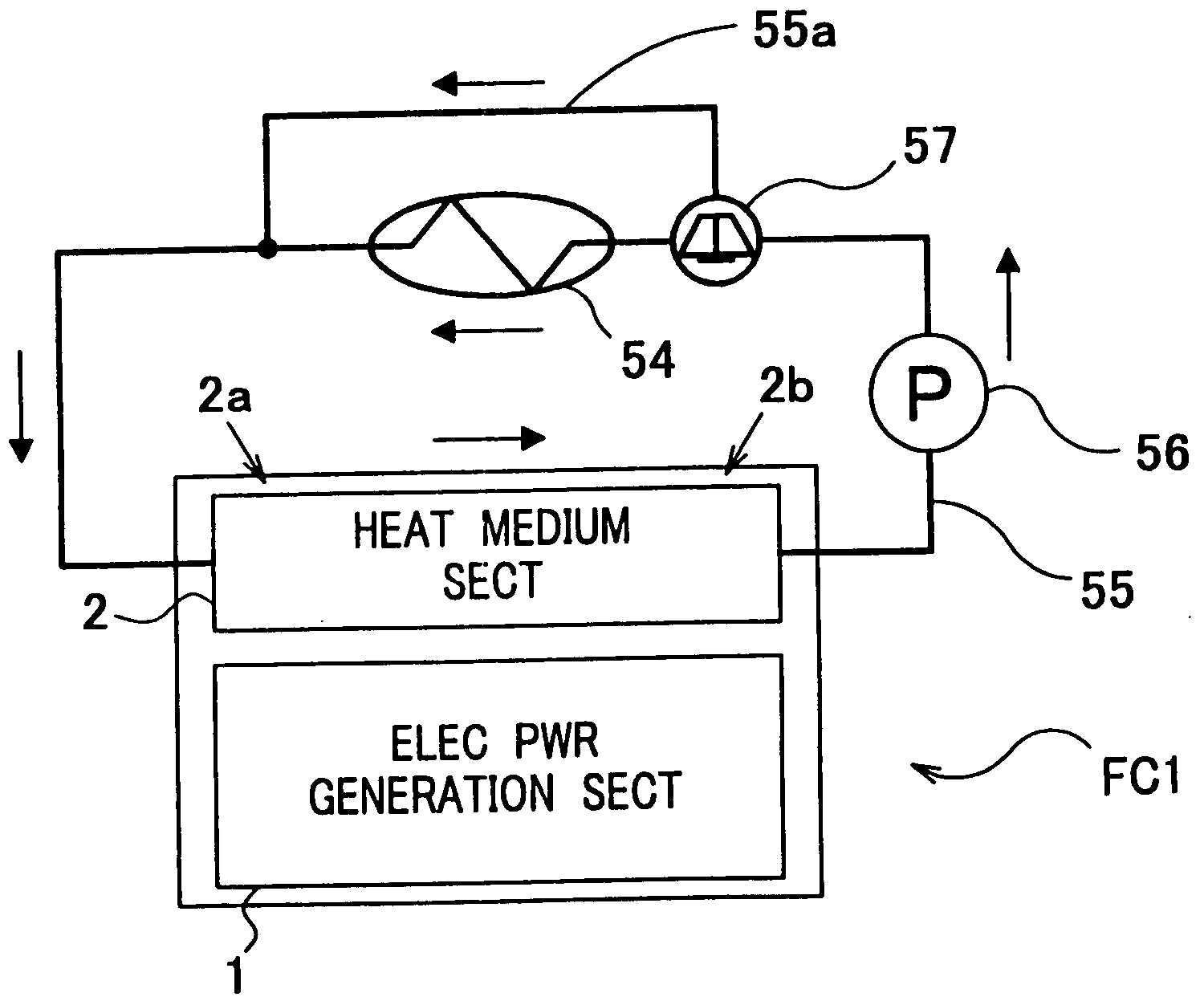
[0019] This structure eliminates the necessity of the flow of the heat medium in the electric power generation section and thus prevents the leak of the heat medium in the electric power generation section. In other words, an electrical conductive coolant can be used as the heat medium. Further, if an ion exchanger is used, this structure may eliminate the periodic replacement of the ion exchange membrane or extends the replacement period.
[0020] This structure provides an electrical conduction between the separators through the heating plate in the lamination direction. The heat plate exchanges heat with at least one of the heat medium passage and a heat medium in the heat medium passage. Further, the electrical insulator provides electrical insulation between the heat plate and the heat medium. This prevents an electric power generation loss due to electrical leakage in the electrical power generation section.
[0022] The heat plate and at least one of the separators adjacent to the heat plate may be connected to have one body. This structure can increase the electrical conductivity and heat exchange efficiency.
[0024] According to this structure, the heat medium may be heated with a high temperature combustion gas. The control means may control an amount of the heat medium supplied from the supplying means to the heat medium passage on the basis of a temperature of the electric power generation section. Thus, the heated heat medium may be supplied to the heat medium passage to heat the separator at the electric power generation section to provide a high-efficient warm-up operation.

Problems solved by technology

In this fuel cell 50, the cooling water may leak in a membrane electrode assembly (MEA) 52 in the fuel cell 50 because the cooling water directly circulating through the fuel cell may cause a trouble or a power generation loss.
Thus, in the fuel cell 50 shown in FIG. 11A, there is a problem that the fuel cell 50 cannot use an electrical conductive coolant (long life coolant), which has been used in the vehicle using an internal combustion engine.
Thus, there is a problem that the pump 56 receives a high load at a low temperature and thus, the efficiency becomes low because the pump 56 should force the coolant having a high viscosity to flow through the narrow grooves 51c in the separators 51a and 51b.
However, the fuel cells disclosed in these documents are cooled by natural circulation of the working liquids in the heat pipes, so that an effective cooling or an effective warm-up operation cannot be provided.

Method used


Image

  • Fuel cell and a temperature control system for the fuel cell
  • Fuel cell and a temperature control system for the fuel cell
  • Fuel cell and a temperature control system for the fuel cell

Examples


first embodiment

[0049] Hereinbelow will be described a first embodiment of the present invention with reference to accompanied drawings.

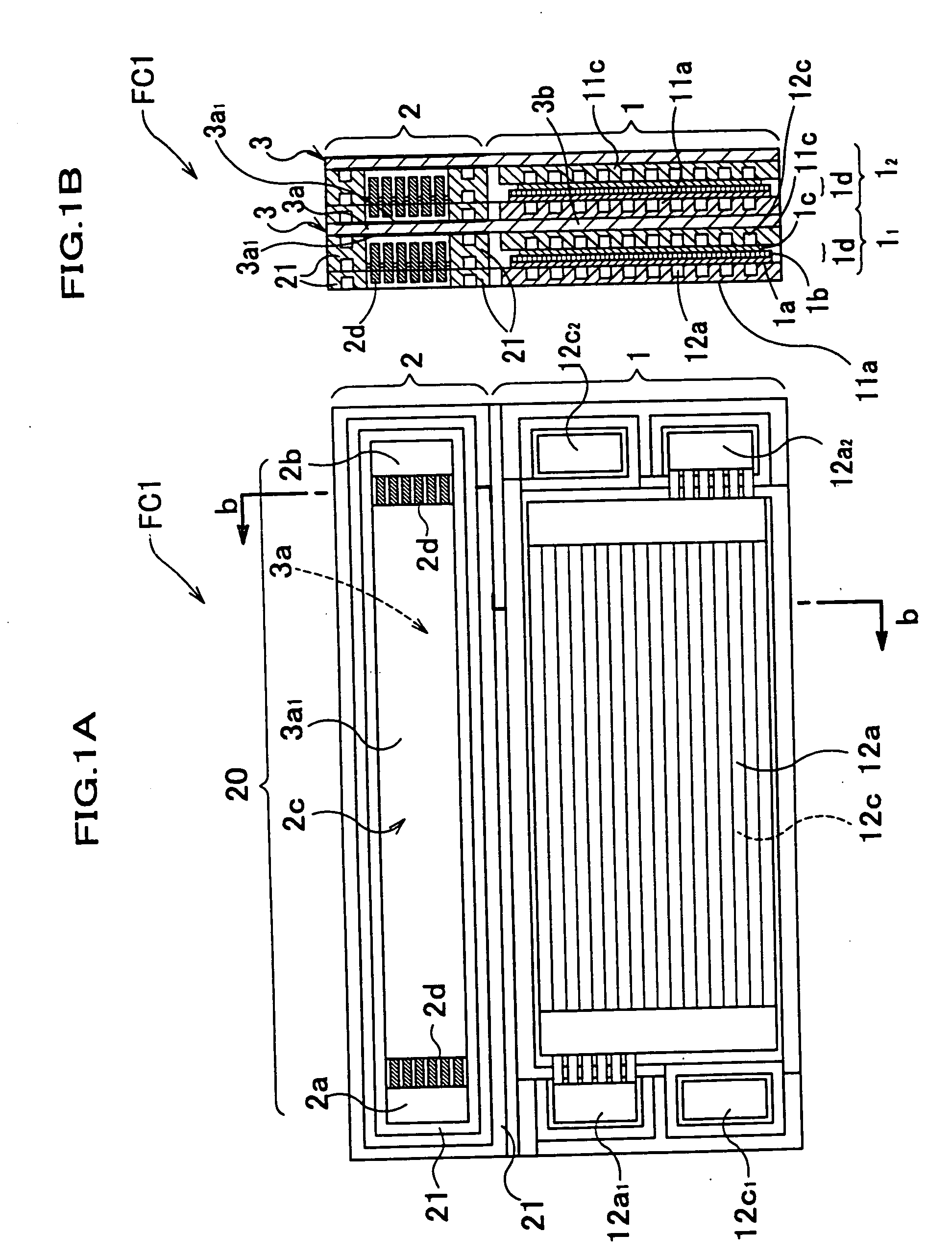
[0050]FIG. 1A is a front elevation cross-sectional view of a fuel cell according to the first embodiment of the present invention schematically illustrating the inside structure of the fuel cell. FIG. 1B is a cross-sectional view, taken along the line b-b in FIG. 1A to show two adjacent unit cells.

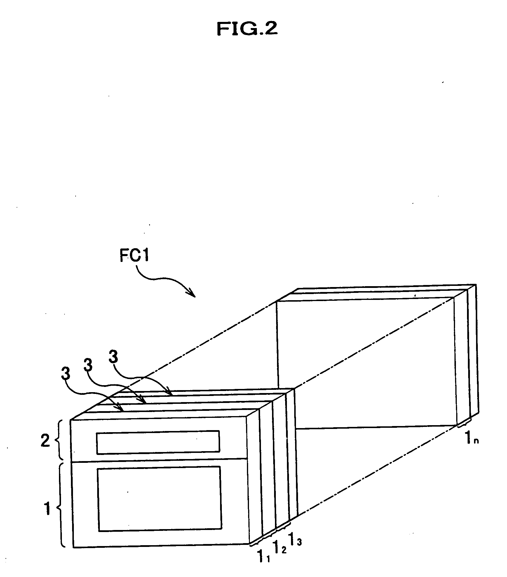
[0051] As shown in FIGS. 1A and 1B, the fuel cell FC1 comprises an electric power generation section 1, a heat medium section 2 separately arranged from the electric power generation section 1 on the top of the electric power generation section 1 (in the drawing), and a heat plate 3 for heat-exchanging between the electric power generation section 1 and the heat medium section 2. Further, the fuel cell FC1 according to the embodiment has a lamination structure as shown in FIG. 2, wherein a plurality of unit cells 11, 12, 13 - - - , and 1n are laminated in a lamination d...

second embodiment

[0087] A fuel cell according to a second embodiment will be described with reference to FIGS. 8A to 10, wherein the corresponding parts or elements to those in the first embodiment are designated with the like references, and thus, the description for these parts or element is omitted. FIG. 8A is a front elevation cross-sectional view of the fuel cell FC2 and FIG. 8B is a sectional view, taken along line c-c in FIG. 8A.

[0088] The fuel cell FC2 according to the second embodiment further comprises a heat medium section 2 under the electric power generation section 1, and the heat plate 3 extends to the lower heat medium section 2. In other words, the electric power generation section 1 is sandwiched between the upper heat medium section 2 and the lower heat medium section 2.

[0089] Respective parts of the under heat medium section 2 are arranged at symmetrical positions, respectively, with respect to the electric power generation section 1. The extended part of the heat plate 3 at th...


PUM


Abstract

A heat medium passage for controlling the temperature of the electric power generation section is separated from the electric power generation section of a fuel cell including a plurality of separators and electric power generating elements alternately laminated in a lamination direction. A heat plate exchanges heat with at least one of the heat medium passage and a heat medium in the heat medium passage and is connected to the separators to provide an electrical conduction between the separators in the lamination direction. An electrical insulator is provided for insulation between the heat medium and the heat plate. Another heat medium passage may be further provided on the other side. A temperature control system for the fuel cell may include a burner for supplying the heated heat medium to the heat medium passage and may comprise first and second fluidic passages independently to selectively use the first and second fluidic passage.

Description

FIELD OF THE INVENTION [0001] This invention relates to a fuel cell and a temperature control system and particularly to a fuel cell with a temperature control using a heat plate and a temperature control system for the fuel cell. BACKGROUND OF THE INVENTION [0002] Fuel cells having a membrane electrode assembly for generating an electric power from a fuel and an oxidizer are known. FIG. 11A shows such a related art fuel cell 50. The fuel cell 50 includes a polymer electrolytic membrane (PEM film) 52b having a proton conductivity, a cathode electrode 52a defined on one side of the polymer electrolytic membrane, and an anode electrode 52c defined on the opposite side, to form a membrane electrode assembly (MEA) 52. Electrochemical reaction between oxygen in the air supplied to the cathode electrode 52a and hydrogen in the fuel gas supplied to an anode electrode 52c generates an electric power. The fuel cell 50 is formed by laminating or stacking a plurality of unit cells 51, each gen...

Claims


Application Information

Patent Timeline
IPC IPC(8): H01M8/02H01M8/04H01M8/10H01M8/24
CPCH01M8/0258H01M8/0267Y02E60/50H01M8/04067H01M8/241H01M8/04022H01M8/2457H01M8/2483
Inventor ENJOJI, NAOYUKIWARIISHI, YOSHINORISASAMOTO, KAZUYAKOSAKA, YUICHIRO
Owner HONDA MOTOR CO LTD
Learn More