
Socket connector assembly with flexible orientation heat pipe

Inactive Publication Date: 2012-07-19
HON HAI PRECISION IND CO LTD
View PDF3 Cites 0 Cited by
  • Summary
  • Abstract
  • Description
  • Claims
  • Application Information

AI Technical Summary

Benefits of technology

[0007]Accordingly, another object of the present invention is to provide a socket connector assembly provided with flexible means asserting downward force evenly to a heat pipe retainer and a protective plate therefore preventing potential warpage of the heat pipe and the IC package.
[0008]To fulfill the above object, a socket connector assembly, adapted for electrically connecting an IC package and a printed circuit board, comprises an insulative housing, a cover plate, a heat pipe retainer embedded with two heat pipes, and a plurality of fastening members. The insulative housing defines a space for the IC package. The heat pipe retainer with the heat pipes are seated on the IC package that received in the insulative housing. The cover plate is upon the heat pipe retainer. The heat pipe retainer is formed with a dowel pin in a center thereof, and the cover plate is formed with a hole receiving the dowel pin, so that the heat pipe retainer is flexibly orientated and can rotates around the hole. The cover plate defines at least one first pressing finger downward pressing an upper surface of the heat pipe retainer so as to exert downward force evenly to a heat pipe retainer therefore preventing potential warpage of the heat pipe.

Problems solved by technology

So a field on the printed circuit board for a heat dissipation which connects the heat pipe is limited.
Moreover, the IC package may be damaged because the lid is directly and rigidly pressed on the IC package.

Method used


Image

  • Socket connector assembly with flexible orientation heat pipe
  • Socket connector assembly with flexible orientation heat pipe
  • Socket connector assembly with flexible orientation heat pipe

Examples


Embodiment Construction

[0017]Reference is now made to the drawings to describe the invention in detail.

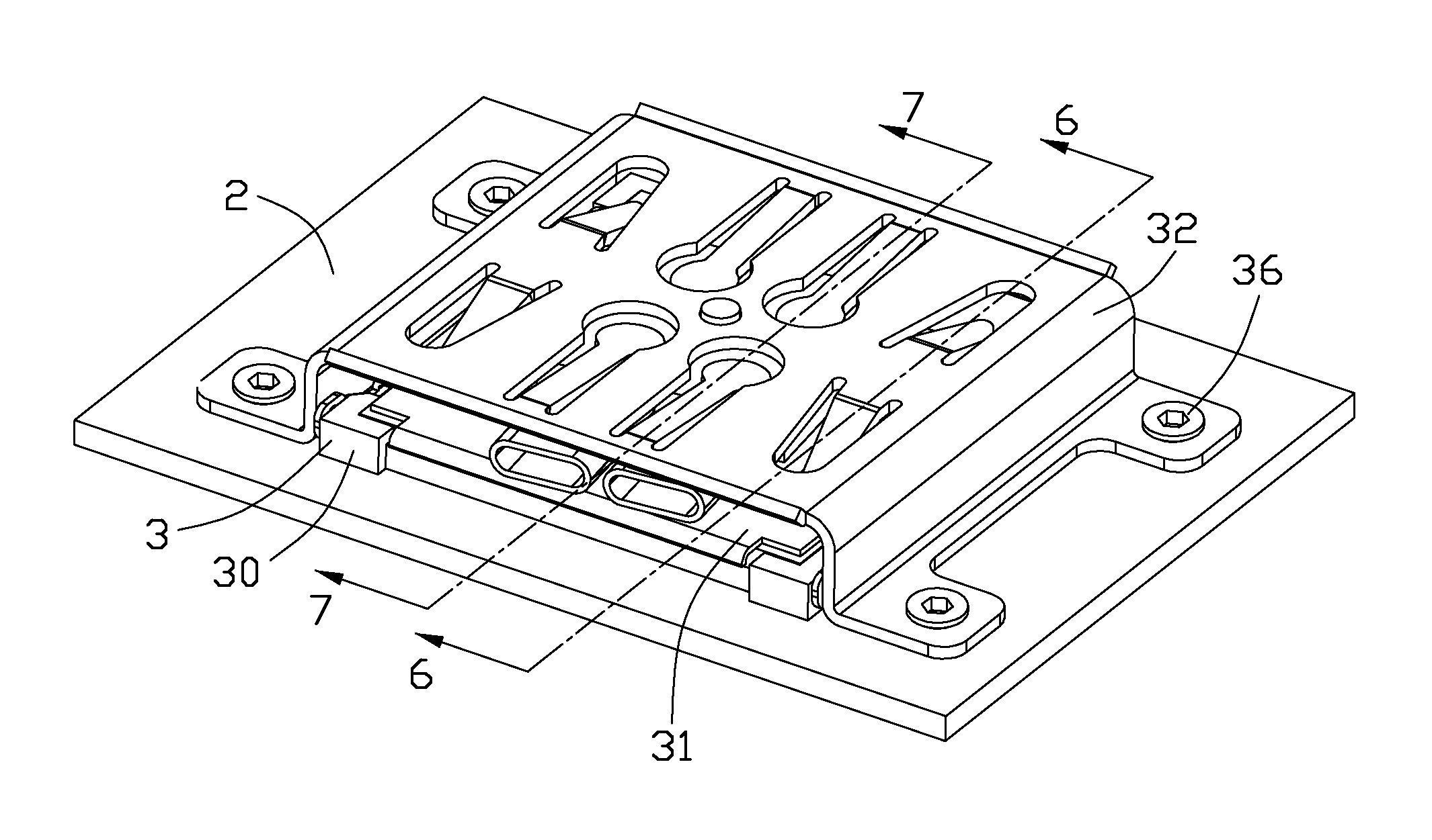
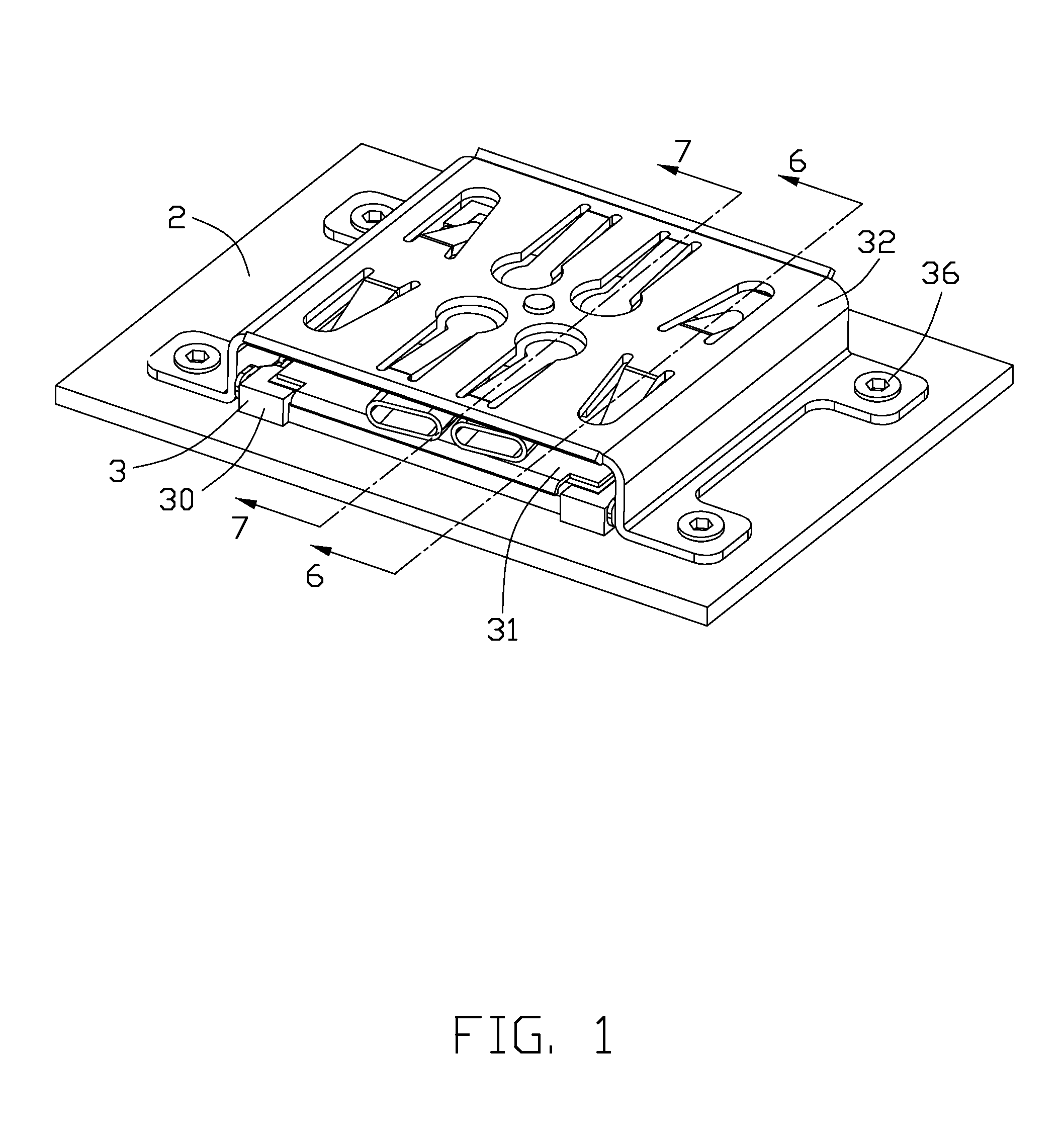
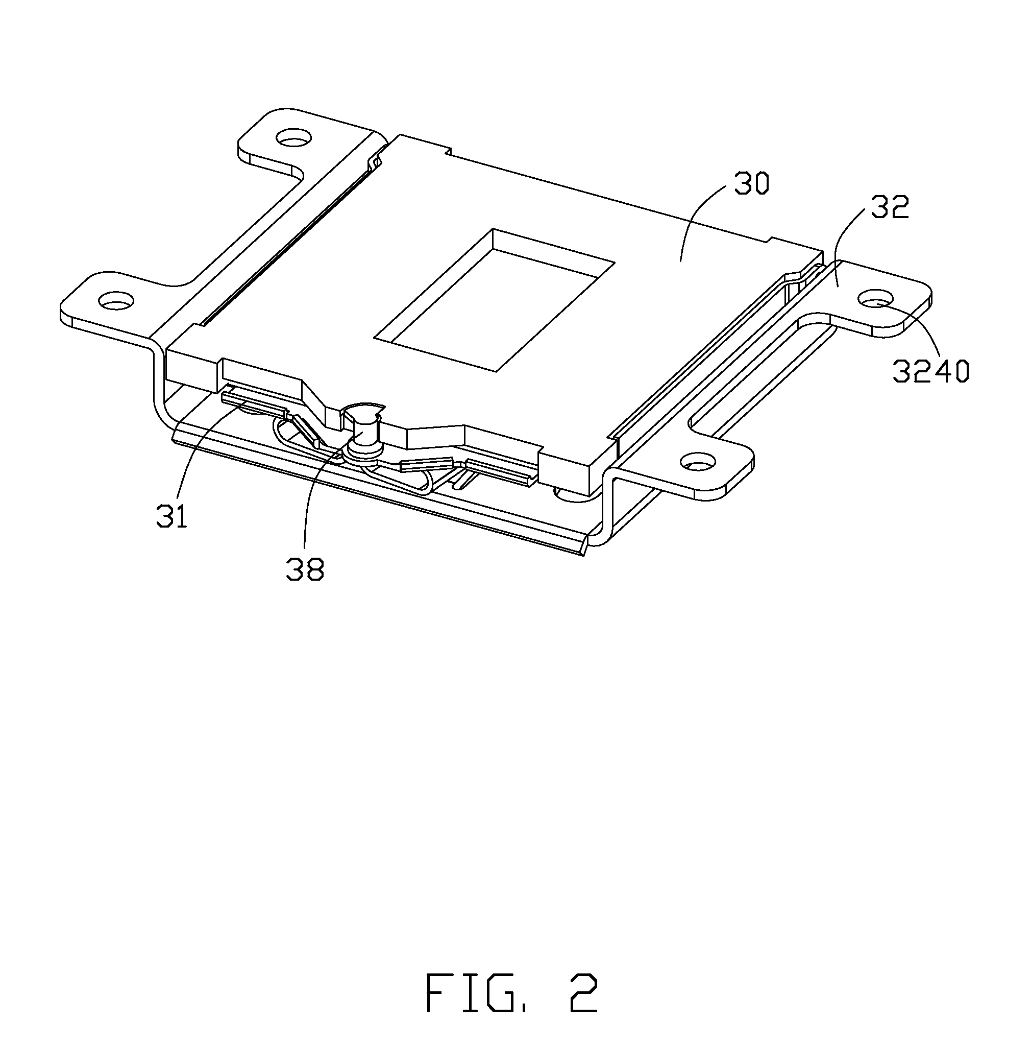
[0018]Referring to FIGS. 1-7, a socket connector assembly 3 in accordance with a preferred embodiment of the present invention is shown, which is adapted for electrically connecting an IC package 1 and a printed circuit board 2.

[0019]The socket connector assembly 3 comprises an insulative housing 30, a protective plate 31, a cover plate 32, a heat pipe retainer 33 embedded with two heat pipes 34, and a plurality of fastening members 36. One end of the protective plate 31 has two connecting portion 310 at opposite edges, which are pivotally mounted on opposite sidewalls of the insulative housing 30 thereby allowing the protective plate 31 rotating between a closed position and an opening position relative to the housing 30. An opposite end of the protective plate 31 defines an extending portion 312 with an opening 3120 thereon. The protective plate 31 further defines a screw member 314 arranged on a lower...


PUM


Abstract

A socket connector assembly, adapted for electrically connecting an IC package and a printed circuit board, comprises an insulative housing, a cover plate, a heat pipe retainer with two heat pipes, and a plurality of fastening members. The insulative housing defines a space for the IC package. The heat pipe retainer with the heat pipes are seated on the IC package received in the insulative housing. The cover plate is upon the heat pipe retainer. The heat pipe retainer is formed with a dowel pin in a center thereof, and the cover plate is formed with a hole receiving the dowel pin, so that the heat pipe retainer is flexibly orientated and can rotates around the hole. The cover plate defines at least one first pressing finger downward pressing an upper surface of the heat pipe retainer so as to exert downward force evenly to a heat pipe retainer therefore preventing potential warpage of the heat pipe.

Description

BACKGROUND OF THE INVENTION[0001]1. Field of the Invention[0002]The present invention relates to a socket connector assembly which is used for connecting an electronic package, such as a central processing unit (CPU), with a circuit substrate, such as a printed circuit board (PCB).[0003]2. Description of the Prior Art[0004]U.S. Pat. No. 7,008,239, issued on Mar. 7, 2006, discloses a socket connector mounted on a printed circuit board (PCB). The socket includes an insulative housing, a plurality of contacts, four screw nuts and four screws, a lid and a heat guide pipe. The insulative housing has a plurality of slots for receiving the contacts and a border projecting therefrom and around the slots for orientating an electronic component, such as an IC module. The screw nuts connect the insulative housing to the PCB from a bottom side of the PCB. The screws engage with the screw nuts from a top side of the PCB. The lid is arranged between the screws and the insulative housing. A head o...

Claims


Application Information

Patent Timeline
IPC IPC(8): H01R13/00
CPCH01R12/73
Inventor WERTZ, DARRELL LYNN
Owner HON HAI PRECISION IND CO LTD
Learn More