
Control system for hybrid vehicle

Active Publication Date: 2016-06-23
TOYOTA JIDOSHA KK
View PDF0 Cites 10 Cited by
  • Summary
  • Abstract
  • Description
  • Claims
  • Application Information

AI Technical Summary

Benefits of technology

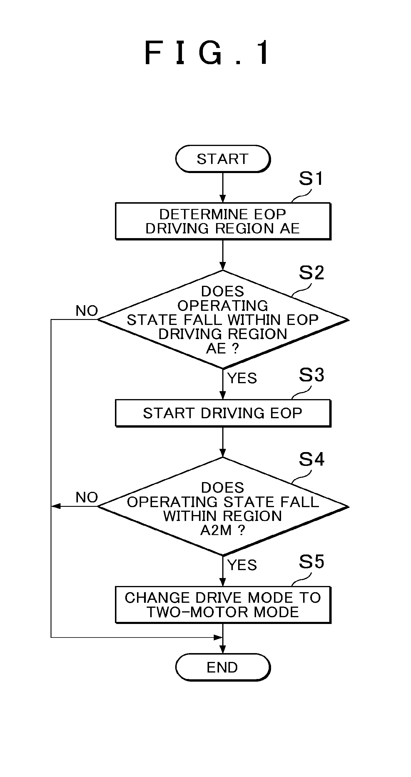
The invention is a control system for a hybrid vehicle that allows it to travel for longer periods of time in a two-motor drive mode and increases the chance of causing the vehicle to enter that mode. The system prevents insufficient lubrication and cooling in the two-motor drive mode by starting to supply oil to the power split mechanism before the mode change. Additionally, the system cools the power split mechanism when the vehicle moves into the first drive mode, reducing its temperature and extending the time the vehicle can stay in the two-motor drive mode.

Problems solved by technology

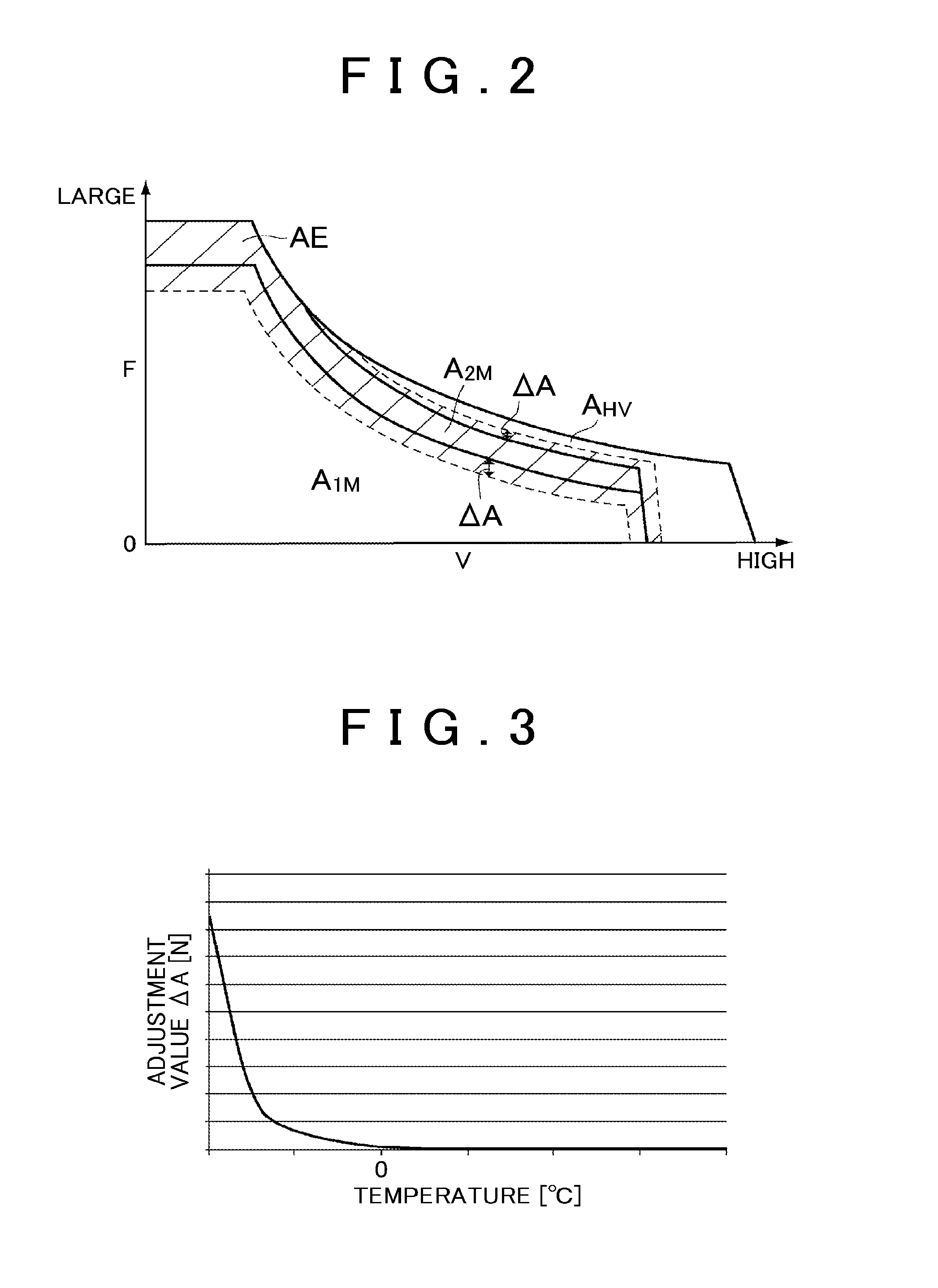
This is because a load on the electric oil pump increases as the viscosity of oil becomes higher and there is a possibility that the durability of the electric oil pump decreases.
On the other hand, there is an inevitable delay from when driving of the electric oil pumps is started to when oil reaches the differential mechanism.
Therefore, when driving of the electric oil pump is started simultaneously with switching of the drive mode to the two-motor mode, the differential mechanism transmits torque in a non-lubricated state or non-cooled state until oil reaches the differential mechanism, so there is a possibility of a decrease in durability.
Alternatively, when the vehicle is caused to travel while another drive mode is set in order to suppress a decrease in the durability of the differential mechanism in this way, there is a possibility that a period during which the hybrid vehicle is allowed to be caused to travel in the two-motor mode shortens or an opportunity to cause the hybrid vehicle to travel in the two-motor mode reduces.

Method used


Image

  • Control system for hybrid vehicle
  • Control system for hybrid vehicle
  • Control system for hybrid vehicle

Examples


Embodiment Construction

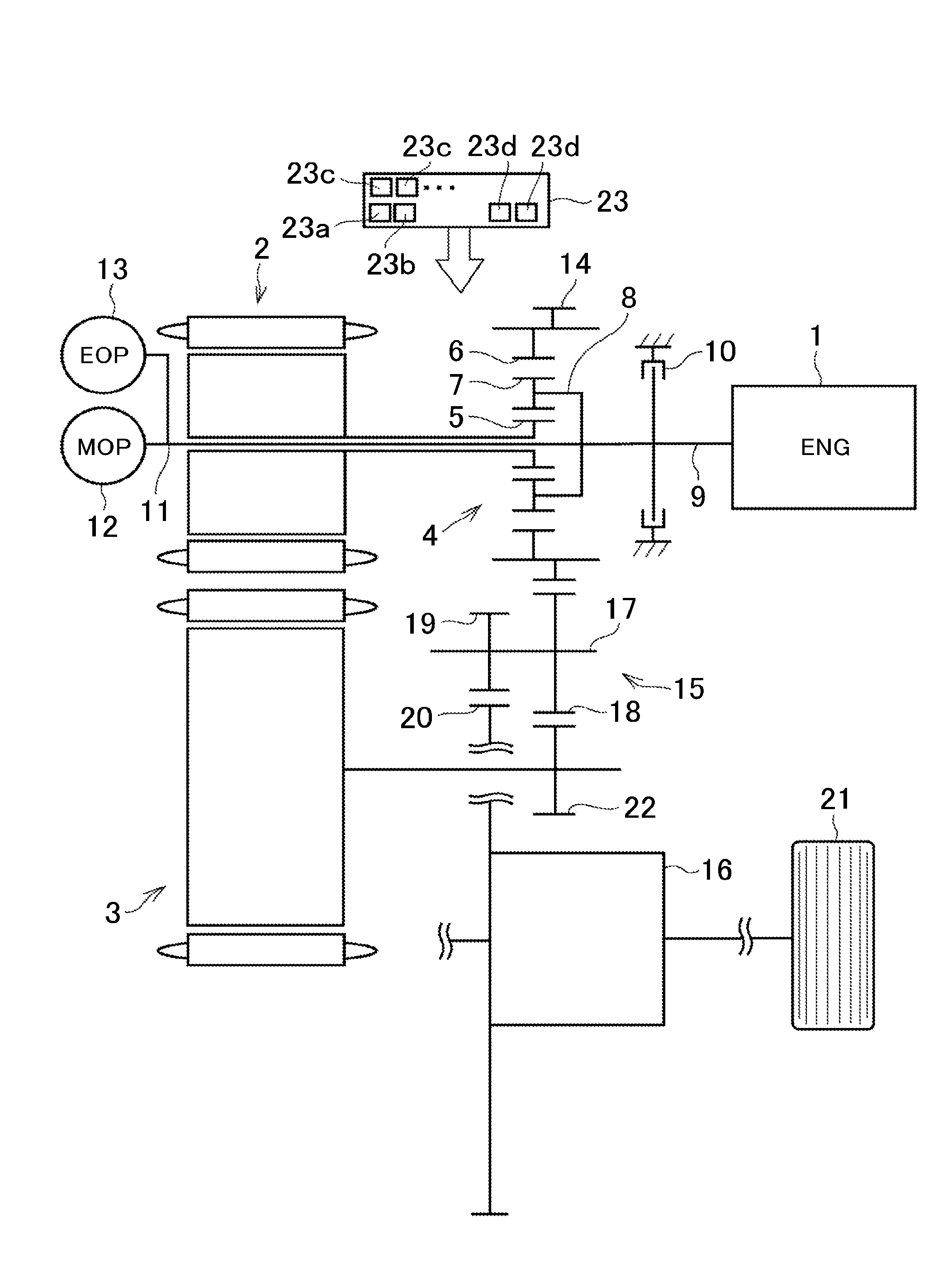
[0035]An example of a hybrid vehicle to which the invention is applicable is shown by a skeletal view in FIG. 9. A hybrid drive system is a so-called two-motor-type drive system, and includes an engine (ENG) 1 and two motors 2, 3 as driving force sources. The engine 1 is an internal combustion engine, such as a gasoline engine and a diesel engine. The first motor 2 may be a motor generator (MG) that is able to regenerate energy or output power. The second motor 3 may be similarly a motor generator (MG). The hybrid drive system includes a power split mechanism 4 that distributes power, output from the engine 1, to the first motor 2 and an output member. The power split mechanism 4 may be formed of a differential mechanism, such as a planetary gear mechanism, and is formed of a single-pinion-type planetary gear mechanism in the example shown in FIG. 9.

[0036]A plurality of (for example, three) pinion gears 7 that are in mesh with a sun gear 5 and a ring gear 6 are arranged between thes...


PUM


Abstract

A control system for a hybrid vehicle includes an electronic control unit. The electronic control unit is configured to, when any one of the following conditions iii) to vi) is satisfied, activate the oil pump to start supplying oil to a power split mechanism: iii) a required driving force becomes larger than or equal to a first pump changing value when a first drive mode is selected; iv) a vehicle speed becomes higher than or equal to a second pump changing value when the first drive mode is selected; v) the required driving force becomes smaller than or equal to a third pump changing value when the third drive mode is selected; and vi) the vehicle speed becomes lower than or equal to a fourth pump changing value when the third drive mode is selected.

Description

INCORPORATION BY REFERENCE[0001]The disclosure of Japanese Patent Application No. 2014-255855 filed on Dec. 18, 2014 including the specification, drawings and abstract is incorporated herein by reference in its entirety.BACKGROUND OF THE INVENTION[0002]1. Field of the Invention[0003]The invention relates to a control system for a hybrid vehicle including an engine and at least two motors or motor generators as driving force sources.[0004]2. Description of Related Art[0005]Japanese Patent Application Publication No. 8-295140 (JP 8-295140 A) and Japanese Patent Application Publication No. 2014-848 (JP 2014-848 A) describe a hybrid vehicle including an engine and two motor generators as driving force sources. In the hybrid vehicle, the engine and the first motor generator are respectively coupled to two rotating elements of a power split mechanism formed of a single-pinion-type planetary gear mechanism, and the second motor generator is coupled to a gear train coupled to drive wheels a...

Claims


Application Information

Patent Timeline
IPC IPC(8): B60W20/15B60W10/30B60W50/06B60W20/40B60L50/16
CPCB60W20/15B60W20/40B60W10/30Y10S903/902B60W2510/0657B60W2710/30B60W50/06B60K6/445B60W10/06B60W10/08B60W20/10B60W2710/08B60W2710/06F16H3/727F16H57/0441F16H57/0446F16H57/0486F16H2037/0866F16H2061/0037F16H61/0031B60K25/02B60K2006/381B60W2510/107B60W30/1843Y02T10/62
Inventor MURATA, SOHEINISHIMINE, AKIKOHATA, KENSEISUZUKI, YOSUKE
Owner TOYOTA JIDOSHA KK
Learn More