Cooling device for internal combustion engine

Active Publication Date: 2016-11-24
DENSO CORP
View PDF5 Cites 1 Cited by
  • Summary
  • Abstract
  • Description
  • Claims
  • Application Information

AI Technical Summary

Benefits of technology

[0010]Since the outflow temperature changes with the temperature of the internal combustion engine, the information about the change rate of the outflow temperature is monitored, and the flow control valve is controlled to be open or closed so as to prevent the change rate of outflow temperature from decreasing to a min

Problems solved by technology

Therefore, a temperature decrease of the internal combustion engine after sta

Method used


Image

  • Cooling device for internal combustion engine
  • Cooling device for internal combustion engine
  • Cooling device for internal combustion engine

Examples


Example

[0014]An embodiment of the present disclosure will be described herein after.

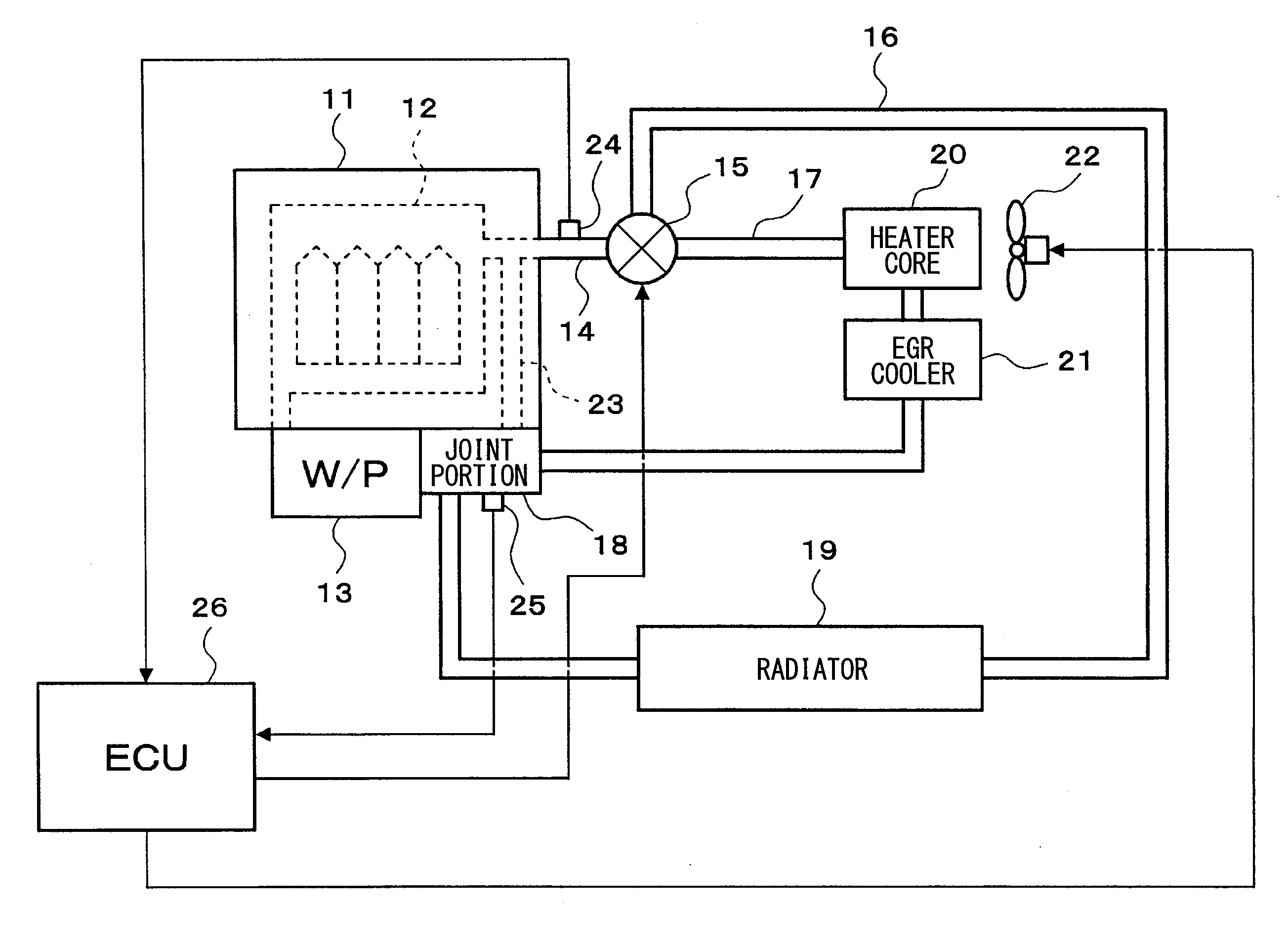
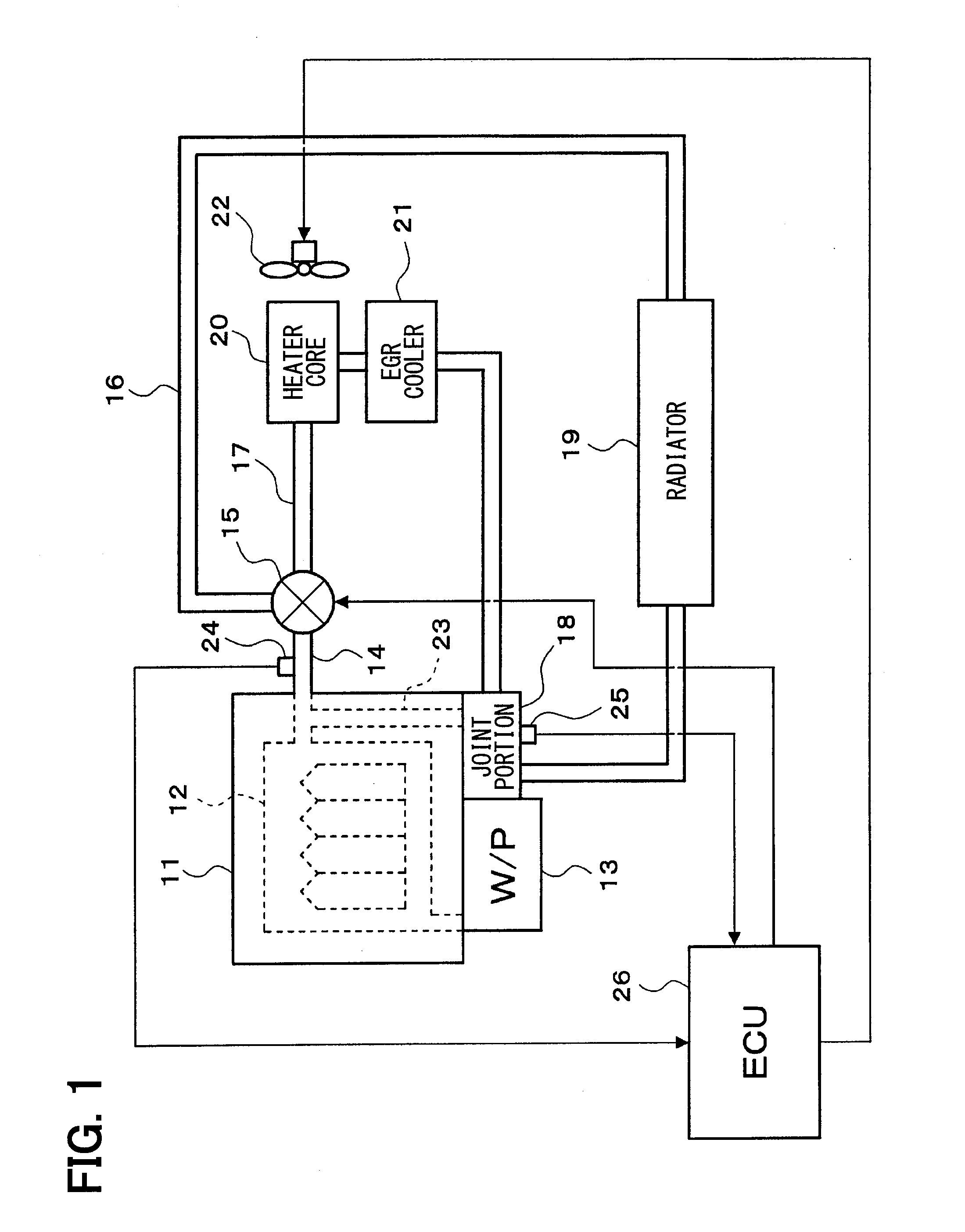
[0015]First, a schematic configuration of an engine cooling system will be described with reference to FIG. 1.

[0016]A water pump 13 for circulating cooling water is provided near an inlet of a water jacket 12 (i.e., cooling water passage) of an engine 11, which is an internal combustion engine. The water pump 13 is a mechanical pump driven by power from the engine 11.

[0017]An outlet passage 14 is connected to an outlet of the water jacket 12 of the engine 11. Connected to the outlet passage 14 are a radiator passage 16 and a bypass passage 17 via a flow control valve 15. The radiator passage 16 is a passage that circulates the cooling water for the engine 11 through a radiator 19. The bypass passage 17 is a passage that circulates the cooling water for the engine 11 to bypass the radiator 19.

[0018]The radiator passage 16 and the bypass passage 17 are connected to a suction port of the water pump 13 via a jo...


PUM


Abstract

A cooling device for an internal combustion engine has an outflow temperature sensor, a flow control valve, and a control device. The outflow temperature sensor detects an outflow temperature of the cooling water flowing out from a cooling-water outlet of the internal combustion engine. The flow control valve adjusts a flow rate of the cooling water flowing in a bypass passage. The control device controls the flow control valve to be open or closed. The control device, during a warming of the internal combustion engine, controls the flow control valve to be open or closed based on information about a change rate of the outflow temperature to prevent the change rate of the outflow temperature from decreasing to a minus value, after opening the flow control valve and starting a circulation of the cooling water in a route passing through the bypass passage.

Description

CROSS REFERENCE TO RELATED APPLICATION[0001]This application is based on Japanese Patent Application No. 2014-033434 filed on Feb. 24, 2014, the disclosure of which is incorporated herein by reference.TECHNICAL FIELD[0002]The present disclosure relates to a cooling device for an internal combustion engine, which includes a bypass passage that circulates cooling water for the internal combustion engine without passing the cooling water through a radiator.BACKGROUND ART[0003]As a cooling device for an internal combustion engine, there is a cooling device including an external passage (i.e., bypass passage) that circulates the cooling water for the internal combustion engine without passing the cooling water through a radiator, to accelerate warming of the internal combustion engine. There is another cooling device which accelerates warming of an internal combustion engine by stopping a circulation of the cooling water during a warming of the internal combustion engine.[0004]However, a...

Claims


Application Information

Patent Timeline
IPC IPC(8): F01P7/16
CPCF01P7/165F01P2037/02F01P2025/32F01P2007/146F01P7/16
Inventor SHIKATA, YASUHIRO
Owner DENSO CORP
Why Eureka
Try Eureka