Devices, systems, and kits for electroporation and methods of use thereof

Pending Publication Date: 2020-04-30
KYTOPEN CORP
View PDF2 Cites 1 Cited by
  • Summary
  • Abstract
  • Description
  • Claims
  • Application Information

AI Technical Summary

Benefits of technology

[0016]In some embodiments, the device further includes one or more additional electroporation zones (e.g., one, two, three, four, six, eight, ten, 11, 12, 24, 27, 36, 48, 64, 96, 384, 1536, or more) additional electroporation zones, which can be configured in parallel, in series, or a combination thereof. The one or more additional electroporation zones can each have a substantially uniform transverse cross-sectional area.
[0017]In some embodiments of any of the aforementioned embodiments, the device can further include a housing configured to encase the first electrode, second electrode, and the electroporation zone. The housing may include a first electrical input operatively coupled to the first electrode and a second electrical input operatively coupled to the secon

Problems solved by technology

This drug discovery process is laborious, requiring significant manual labor within the laboratory, creating an industry-wide bottleneck due to the lack of adequate high-throughput technologies.
However, transfection steps are limited to low throughput, poor efficiency technologies, and user-intensive systems that cannot be automated.
Existing viral techniques to deliver DNA appear on par with electroporation, but there is a lack of GMP-quality non-retroviral RNA viruses.
While a viral methodology can be applied to high-throughput automated systems, there are limitation

Method used


Image

  • Devices, systems, and kits for electroporation and methods of use thereof
  • Devices, systems, and kits for electroporation and methods of use thereof
  • Devices, systems, and kits for electroporation and methods of use thereof

Examples


example 1

Devices and Systems

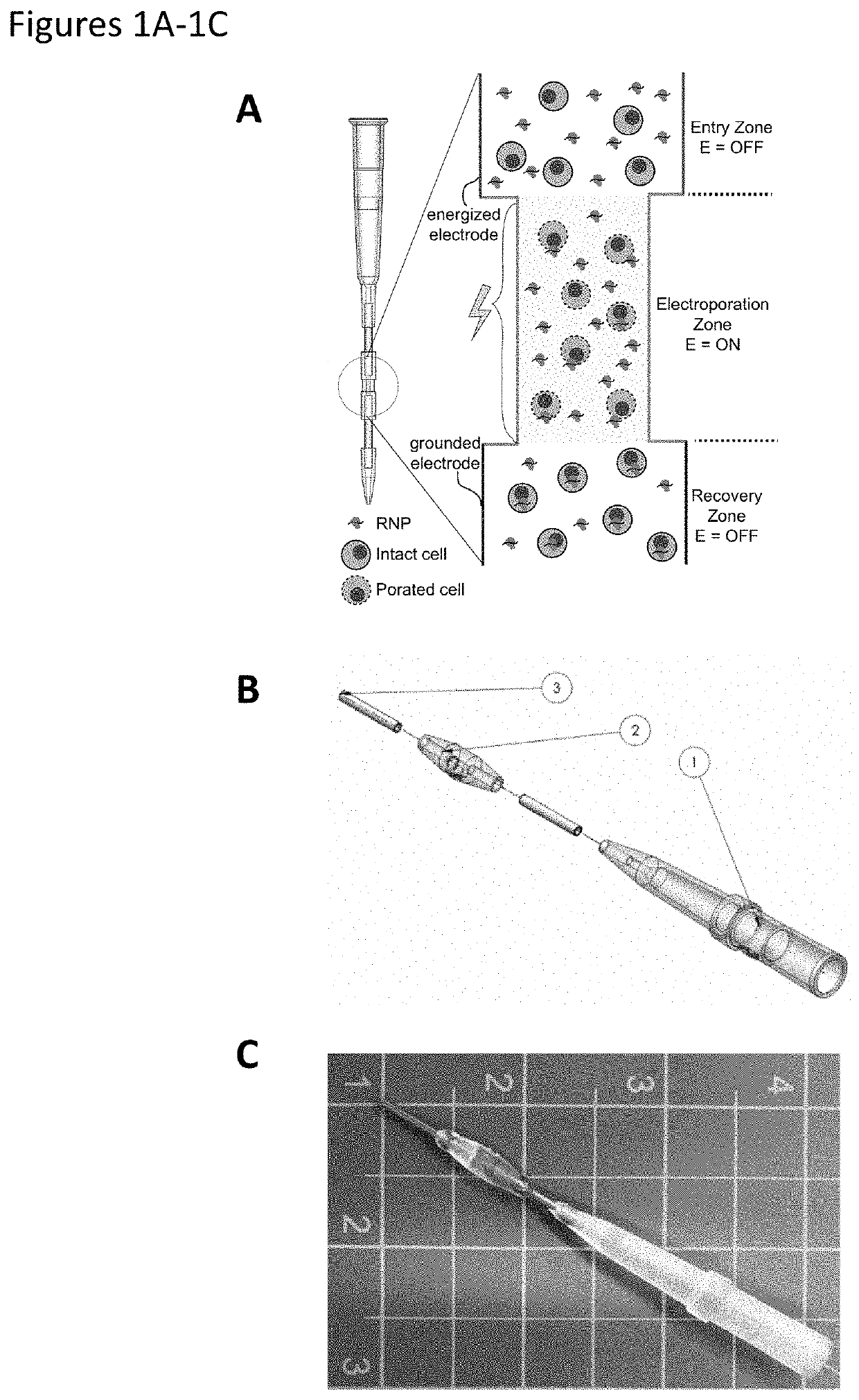
[0257]A continuous flow electroporation device and related system were designed and fabricated to allow for a plurality of devices to be used in parallel to enhance or maximize the number of cell electroporation events occurring in a fixed time window, thereby enhancing or maximizing throughput of cell engineering and / or accelerating biological discovery. The electroporation device is configured to be compatible with current automated fluid handling systems, e.g., pipette tip-based dispensers, robotic fluid pumps, etc.

[0258]FIG. 1A shows a schematic of an exemplary embodiment of an electroporation device shown, in this configuration, as a pipette tip. FIG. 1A shows a close-up view of an active area of the device, including an electroporation zone. This device provides for continuous flow genetic manipulation of both eukaryotic and prokaryotic cells in a platform that can be easily automated through integration with liquid handling robots. In the device of FIGS. 1A...

example 2

Initial Development of Experimental Parameters for Optimal Transfection

[0262]Experiments have been conducted to study the physical and biological parameters influencing electroporation of the Jurkat immortalized T cell line using devices of the current invention. Using industry standard flow cytometry methods, both cell viability (measured by 7AAD dye exclusion) and transfection efficiency (measured by GFP expression) of engineered Jurkat cells were assessed using our devices, both of which are common measures of electroporation success in the field of gene delivery. Unless specified otherwise, experimental results shown below were generated by electroporating a population of Jurkat cells at a concentration of 1×10⁶ cells in 100 μL of buffer with 5 μg of plasmid (e.g., GFP expression plasmid). Electroporation experiments were performed at 100 Hz with square waveforms and a pulse duration of 9.5 ms. After 24-hour incubation, cells were stained with 7-AAD stain and analyzed via flow c...

example 3

Transfection Data Using Devices of the Invention

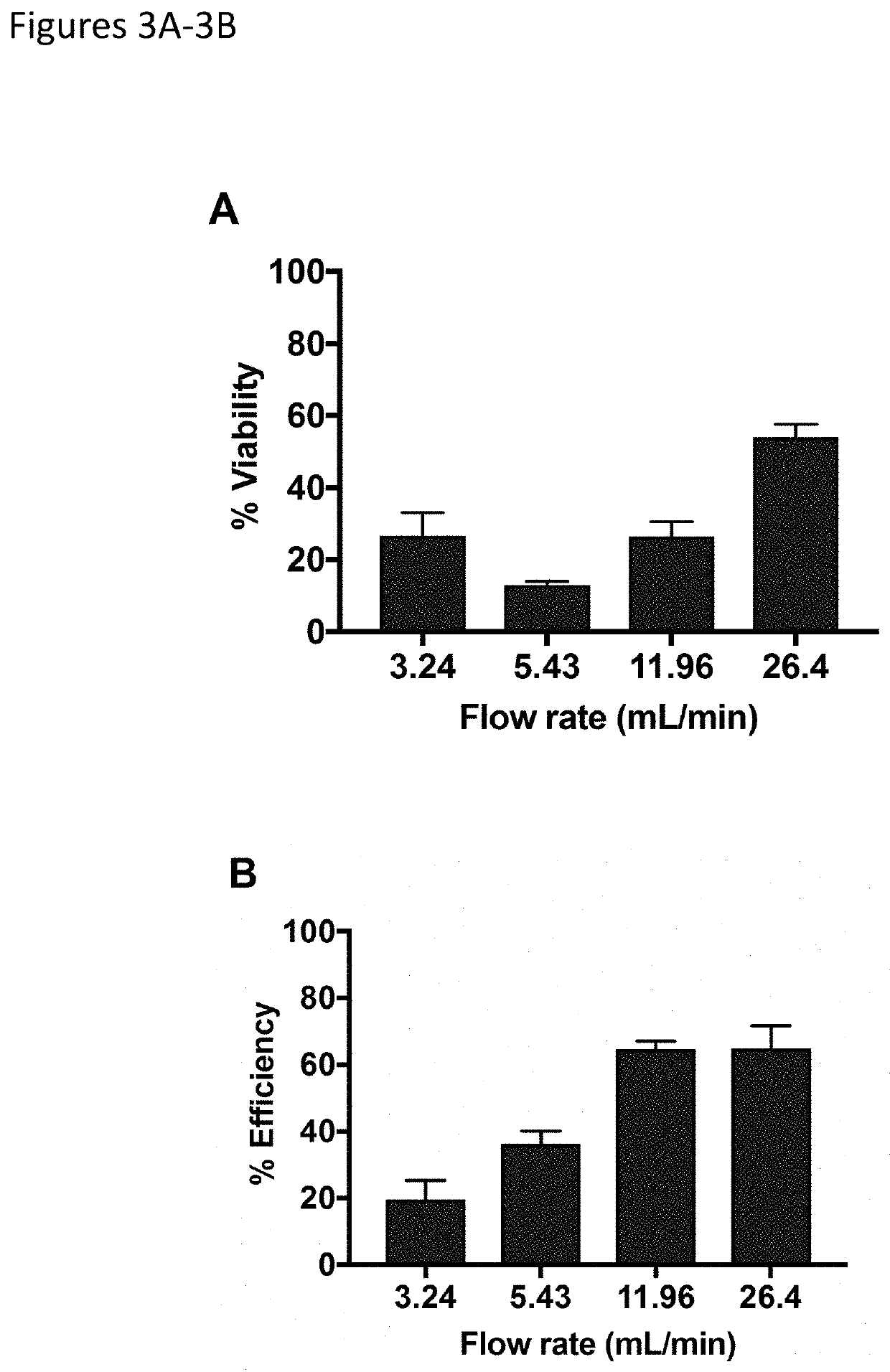
[0263]Devices of the invention show peak transfection performance when the flow rate is maximized through the electroporation channel (FIGS. 3A and 3B). The desired flow rate was achieved utilizing a controlled dispense rate pipette to increase both viability and efficiency, corresponding to a ˜6.5 ms residence time of the cell sample within the electric field. Peak cell viability of 54% was achieved, with transfection efficiency of 65%, demonstrating a significant advancement in the transfection of human immune cells with devices of the invention.

[0264]FIGS. 4A-4D illustrate flow rate simulation along an exemplary active zone of the device (i.e., from a first electrode lumen, through the electroporation zone, and into the second electrode lumen). In this embodiment, a medium contains flowing biological cells. From the simulated fluid flow at 10 mL / min and 100 mL / min, the average linear velocity of the samples going through the electro...


PUM


Abstract

Devices, systems, and kits for cell electroporation are provided. A device includes a first electrode, a second electrode, and an electroporation zone therebetween where an electrical potential difference applied to the first and second electrodes generates an electric field in the electroporation zone sufficient to electroporate at least a subset of the cells in the flow path. Methods of introducing a composition into at least a portion of a plurality of cells using the devices, systems, and kits of the invention are also provided.

Description

STATEMENT OF FEDERALLY SPONSORED RESEARCH[0001]This invention was made with government support under Phase I SBIR Grant No. 1747096 and Phase II SBIR Grant. No 1853194 from the National Science Foundation (NSF). The government has certain rights in the invention.BACKGROUND OF THE INVENTION[0002]Immunotherapy is currently at the cutting edge of both basic scientific research and pharmaceutically driven clinical application. This trend is in part due to the recent strides in targeted gene modification and the expanded use of CRISPR / Cas complex editing for therapeutic development. In order to identify genetic modifications of therapeutic interest, research organizations often have to screen thousands of genetic variants, which can include modification of an endogenous gene or insertion of an engineered gene. This drug discovery process is laborious, requiring significant manual labor within the laboratory, creating an industry-wide bottleneck due to the lack of adequate high-throughput...

Claims


Application Information

Patent Timeline
IPC IPC(8): C12N13/00C12M1/42A61N1/32
CPCA61N1/327C12M1/42C12M35/02C12N13/00C12N15/87
Inventor GARCIA, PAULO ANDRESSIDO, JESSICAHEMPHILL, JAMESMCCORMACK, RAMEECHBRALOWER, HARRISON
Owner KYTOPEN CORP
Why Eureka
Try Eureka