
Method of molding and manufacturing for fluidic device reagent testing cartridge and pods

Pending Publication Date: 2022-04-21
ENPLAS CORP
View PDF0 Cites 3 Cited by
  • Summary
  • Abstract
  • Description
  • Claims
  • Application Information

AI Technical Summary

Benefits of technology

This patent aims to improve the stability and functionality of reagents in an assay cartridge. The invention includes a design with multiple chambers for storing reagents, a middle portion to reduce stress and prevent molding defects, and a hygroscopic element to extend the detection period of the reagent. Additionally, a dummy material can be included to slow the wetting process by the fluid, while an inert gas can be included to decrease contamination. Overall, this design improves the shelf life and reliability of the assay cartridge.

Problems solved by technology

However, a lyophilized reagent is vulnerable to fluids and moisture in the cartridge.
Also, molded cartridges are vulnerable to cracks and defects depending on the chamber thickness.
Due to these vulnerabilities, any manufacturing defects in conventional cartridges, environmental conditions, or a combination thereof, can cause lyophilized reagents or assay materials to be diluted, contaminated, eroded, or otherwise corrupted in ways that can reduce or eliminate their efficacy over time.
Such problems can result in economic losses for testing facilities that need to dispose of materials that become unusably corrupted before they can be deployed.
Additionally, if such compromised materials are used for actual testing, potentially inaccurate and unreliable test results may ensue.

Method used


Image

  • Method of molding and manufacturing for fluidic device reagent testing cartridge and pods
  • Method of molding and manufacturing for fluidic device reagent testing cartridge and pods
  • Method of molding and manufacturing for fluidic device reagent testing cartridge and pods

Examples


Embodiment Construction

[0034]This specification discloses one or more embodiments that incorporate the features of this present invention. The disclosed embodiment(s) merely exemplify the present invention. The scope of the invention is not limited to the disclosed embodiment(s). The present invention is defined by the claims appended hereto.

[0035]The embodiment(s) described, and references in the specification to “one embodiment,”“an embodiment,”“an example embodiment,” etc., indicate that the embodiment(s) described may include a particular feature, structure, or characteristic, but every embodiment may not necessarily include the particular feature, structure, or characteristic. Moreover, such phrases are not necessarily referring to the same embodiment. Further, when a particular feature, structure, or characteristic is described in connection with an embodiment, it is understood that it is within the knowledge of one skilled in the art to effect such feature, structure, or characteristic in connectio...


PUM


Abstract

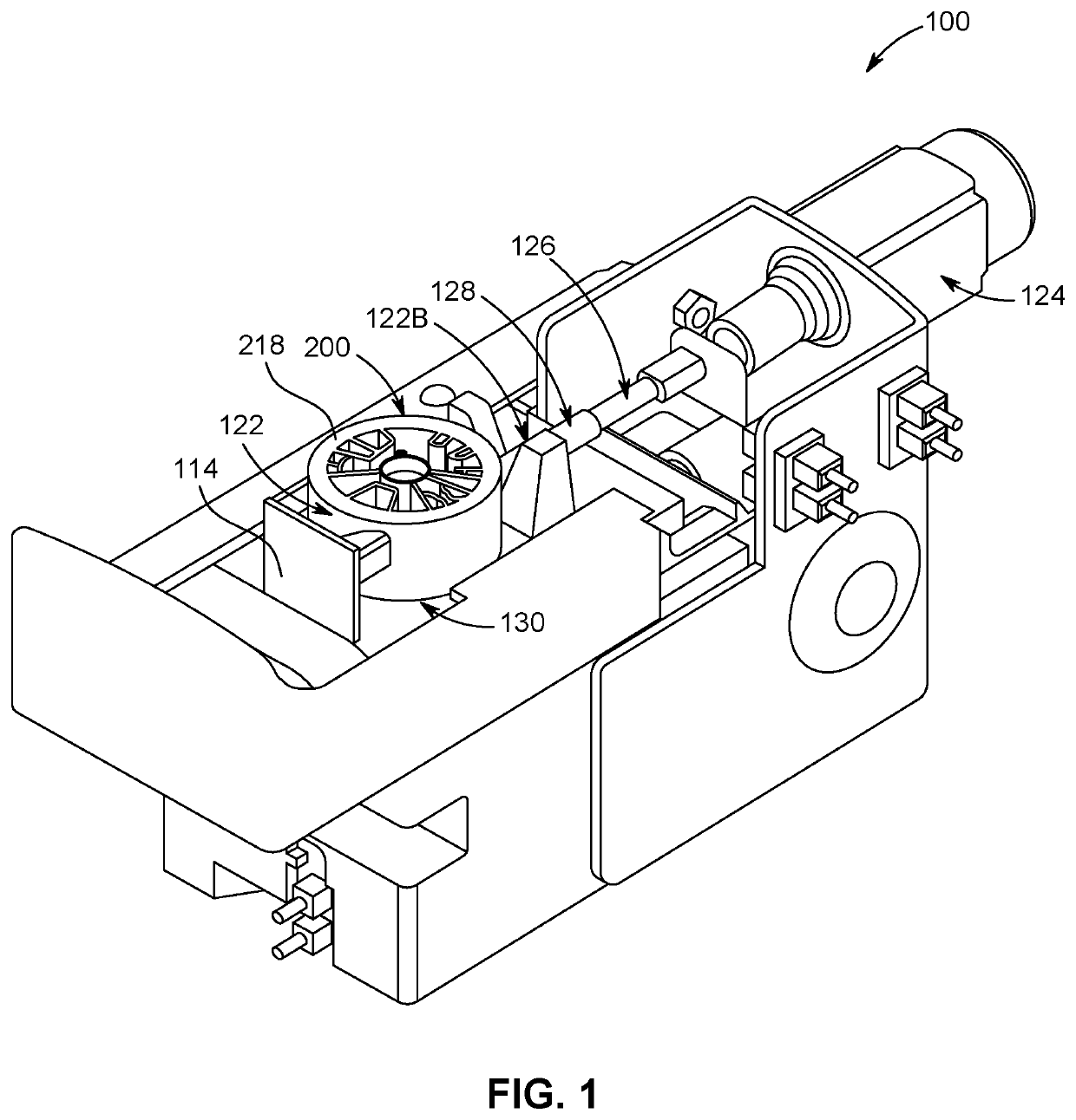
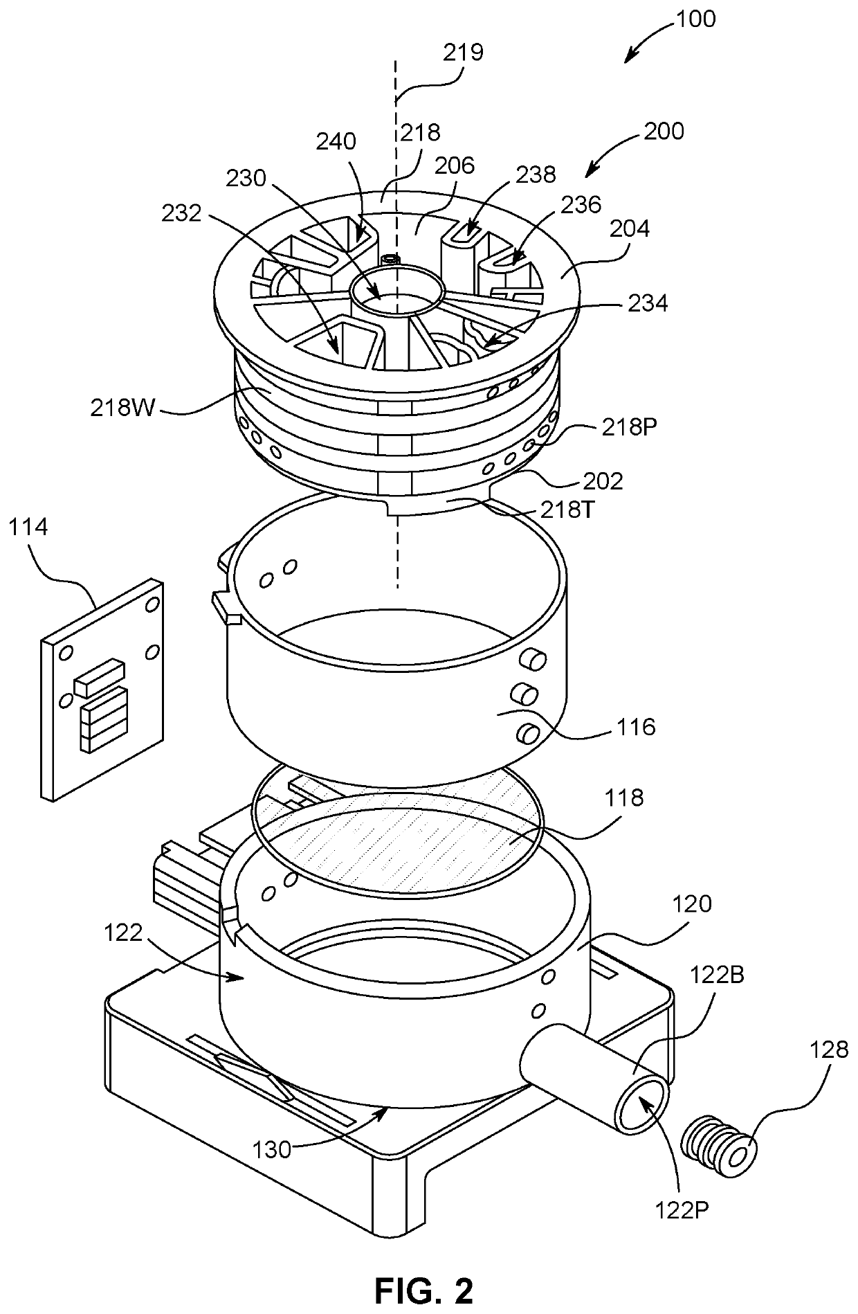
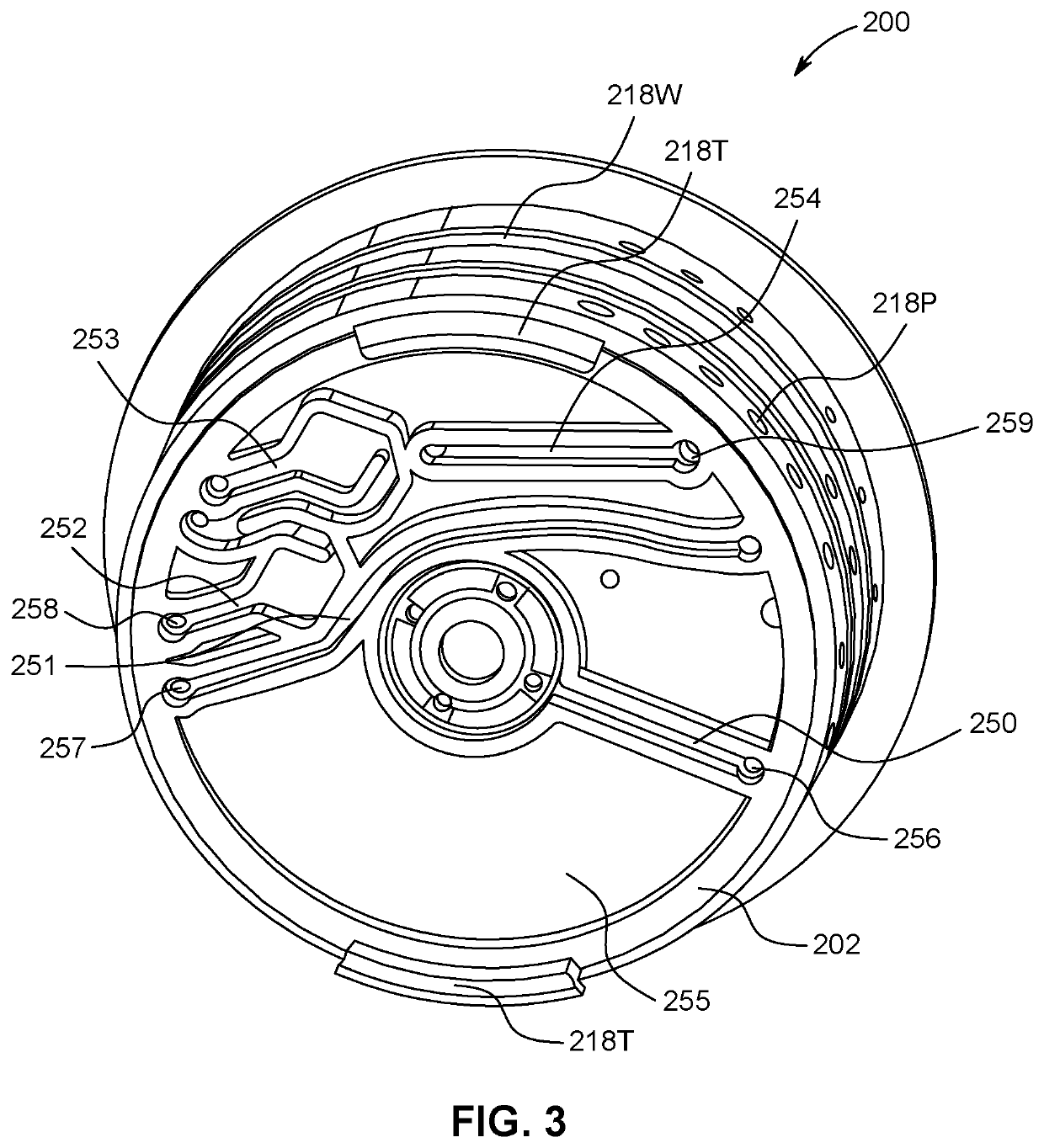
A cartridge for detecting one or more characteristics of a fluid in a diagnostic assay system includes a plurality of chambers. At least one of the plurality of chambers includes a wall. The wall includes an intermediate portion disposed between an exterior surface and an interior surface of the wall. The intermediate portion can include a hygroscopic element configured to extend an active period of detection of a reagent. The intermediate portion can include a dummy material configured to slow a wetting of a reagent by the fluid. The intermediate portion can include an air gap configured to reduce internal stress and / or strain in the cartridge. A reagent can be enclosed by the wall of the at least one of the plurality of chambers. The reagent can be a lyophilized reagent.

Description

CROSS REFERENCE TO RELATED APPLICATIONS[0001]This application is a continuation-in-part of U.S. application Ser. No. 17 / 072,269, filed Oct. 16, 2020, which is hereby incorporated herein in its entirety by reference for all purposes.FIELD[0002]The present disclosure relates to cartridges, for example, disposable assay cartridges and related apparatuses, systems, and methods for making and using such cartridges. Example applications for related cartridges include uses in portable assay systems for fluidic reagent testing.BACKGROUND[0003]Fluid analysis of biological substances for assay testing and detection can require a series of processing steps. These processing steps can require that a particular fluid or fluids contact a reaction area at different times and in varying succession. A single fluid sample can be subjected to a variety of processes or steps prior to contact with a reaction area.[0004]A recent development in the field of diagnostic testing includes a portable diagnosti...

Claims


Application Information

Patent Timeline
IPC IPC(8): B01L3/00
CPCB01L3/502B01L3/508B01L2200/025B01L2200/04B01L2200/0689B01L2400/049B01L2200/141B01L2300/042B01L2300/0609B01L2300/105B01L2200/16G01N33/48B01L3/527B01L2200/027B01L2200/0621B01L2300/0832B01L2300/0803B01L2300/0663B01L2300/0858B01L2300/087B01L2400/0478
Inventor MORIKOSHI, DAISUKE
Owner ENPLAS CORP
Learn More