Power conversion apparatus

Active Publication Date: 2020-11-05
ACER INC
View PDF0 Cites 0 Cited by
  • Summary
  • Abstract
  • Description
  • Claims
  • Application Information

AI Technical Summary

Benefits of technology

The patent text describes a power conversion apparatus that can extend the time it takes to shut down after being powered off. This is achieved by using a backup power source stored by the apparatus to supply power to a control signal generator. This means that the apparatus can maintain its output voltage for a longer period of time after being powered off. The technical effect is that it provides a more reliable and continuous source of power for control signals, even during power loss or other failures.

Problems solved by technology

Nevertheless, since the capacitance of the voltage regulator capacitor of the PWM control chip is usually small, when the power conversion apparatus is powered off suddenly, the PWM control chip is powered off as well and thus stops controlling on and off of the power switch.
Therefore, the insufficient hold-up time problem occurs in most of the existing power conversion apparatuses, and as such, operational stability of electronic apparatuses is lowered.

Method used


Image

  • Power conversion apparatus
  • Power conversion apparatus
  • Power conversion apparatus

Examples


Embodiment Construction

[0015]In order to make the disclosure more comprehensible, several embodiments are described below as examples of implementation of the disclosure. Moreover, wherever possible, elements / components / steps with the same reference numerals are used to represent the same or similar parts in the drawings and embodiments.

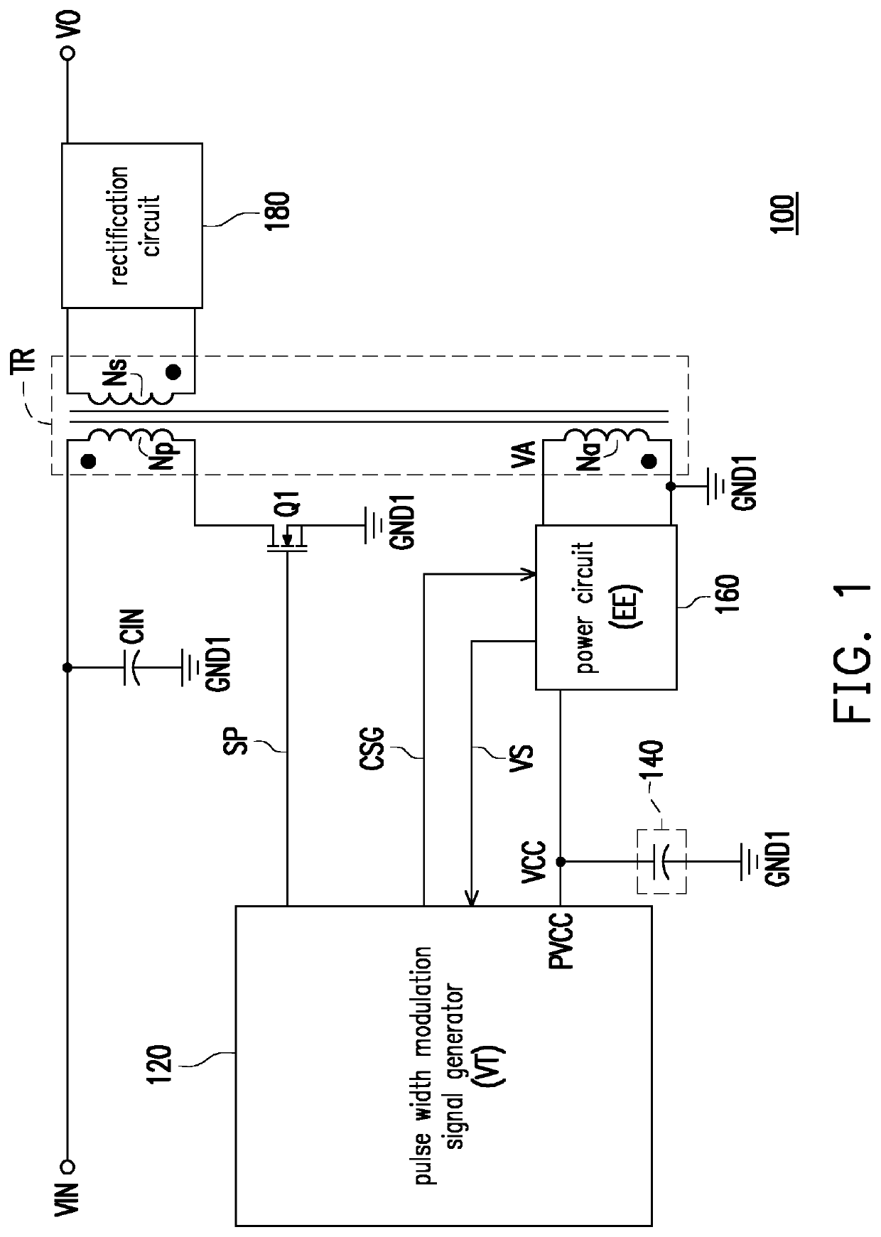
[0016]FIG. 1 is a schematic block diagram of circuits of a power conversion apparatus 100 according to an embodiment of the disclosure. With reference to FIG. 1, the power conversion apparatus 100 may include a transformer TR, a power switch Q1, a pulse width modulation (PWM) signal generator 120, an energy storage element 140, and a power circuit 160, which should however not be construed as a limitation in the disclosure. In an embodiment of the disclosure, the power conversion apparatus 100 may further include an input capacitor CIN and a rectification circuit 180.

[0017]The transformer TR has a primary winding Np, a secondary winding Ns, and an auxiliary winding Na. The...


PUM


Abstract

A power conversion apparatus including a transformer, a power switch, a pulse width modulation (PWM) signal generator, an energy storage element, and a power circuit is provided. A primary winding of the transformer receives an input voltage from an external power source. An auxiliary winding of the transformer provides an auxiliary voltage. The power switch is coupled to the primary winding. The PWM signal generator generates a PWM signal to control on and off the power switch. The energy storage element is coupled to a power terminal of the PWM signal generator. The power circuit supplies power to the PWM signal generator and charges the energy storage element according to the auxiliary voltage. When a voltage of the energy storage element is greater than or equal to a threshold voltage, the power circuit stores backup power according to the auxiliary voltage. When the external power source stops providing the input voltage, the power circuit supplies power to the PWM signal generator and charges the energy storage element according to the backup power.

Description

CROSS-REFERENCE TO RELATED APPLICATION[0001]This application claims the priority benefit of Taiwan patent application serial no. 108115011, filed on Apr. 30, 2019. The entirety of the above-mentioned patent application is hereby incorporated by reference herein and made a part of this specification.BACKGROUNDTechnical Field[0002]The disclosure relates to a power conversion apparatus. More particularly, the disclosure relates to a power conversion apparatus capable of extending a hold-up time length of an output voltage provided by the power conversion apparatus.Description of Related Art[0003]In a power conversion apparatus, an input voltage provided by an external power source could be converted to a DC voltage suitable for any kinds of electronic apparatuses. Therefore, power conversion apparatuses are widely used in electronic apparatuses, such as computers, office automation equipment, industrial control equipment, and communication equipment.[0004]In a power conversion apparatu...

Claims


Application Information

Patent Timeline
IPC IPC(8): H02M3/335
CPCH02M2001/0096H02M3/33507H02M1/0006H02M1/0096
Inventor CHAN, TZU-TSENG
Owner ACER INC
Why Eureka
Try Eureka