Diagnostic Method for an Internal Combustion Engine Exhaust Gas System that includes a Particle Filter

Active Publication Date: 2011-05-05
VITESCO TECH GMBH +1
View PDF6 Cites 18 Cited by
  • Summary
  • Abstract
  • Description
  • Claims
  • Application Information

AI Technical Summary

Benefits of technology

[0013]If the differential pressure values of the second set of value vectors are outside a preset or presettable confidence interval relative to the reference characteristic values, a flow anomaly is possibly diagnosed. (For this comparison, temperature-standardized or de-standardized pressure values can be consulted; pressure values of the second set of value vectors with corresponding pressure values calculated back from reference characteristic values related to the present temperatures are preferred.) If no irregularities are determined during the evaluation of the comparison result, new characteristics or reference characteristics are generated from the values of the second set of value vectors, and stored. In this manner, updated characteristics which are adapted to the respective conditions are continuously available. This has the advantage that erroneous diagnostics due to long term drift effects can be avoided and normal gradually occurring changes are not erroneously diagnosed as a flow anomaly,
[0014]The determination of three different pressure values (that is, the absolute pressure on the inlet side and the outlet side of the particle filter, and the differential pressure over the particle filter) provided according to the invention is especially advantageous. It facilitates a differentiating evaluation at least with regard to leakage of an exhaust gas line section downstream of the particle filter, leakage of an exhaust gas line conducting section upstream of the particle filter, and a breakage of the particle filter in the arrangement of the invention, Especially, evaluation of comparison results obtained separately for the two absolute pressure values and for the differential pressure with regard to the stored reference characteristic values, facilitates a differentiation of the mentioned flow anomalies. This technique has proved to be particularly advantageous in practice, because it avoids an unnecessary change of a particle filter erroneously diagnosed as being broken. Such an erroneous diagnosis is especially possible, if a leakage occurs in an exhaust gas line section upstream of the particle filter, with a lowering of a back pressure on the inlet side of the particle filter resulting therefrom. With an exclusively differential pressure sensing, for example by a differential pressure sensor, the danger of an erroneously diagnosed filter breakage becomes large, with a corresponding high probability of incurring the cost of an unnecessary filter change.
[0015]In a further embodiment of the method according to the invention, clogging of the particle filter and/or an exhaust gas cleaning unit connected upstream or downstream of the particle filter is evaluated. For recognizing these flow anomalies, the determination of the three different pressure values provided according to the invention is again advantageous. In particular, determination of the absolute pressure downstream of the partic

Problems solved by technology

However, such filtering leads to clogging of the particle filter over time, so that flow-through resistance increases in an undesired manner.
Such an erroneous diagnosis is especially possible, if a leakage occurs in an exhaust gas line section upstream of the particle filter, with a lowering of a back pressure on the inlet side of the particle filter resulting therefrom.
With an exclusively differential pressure sensing, for example by a differential pressure sensor, the danger of an erroneously diagnosed filter breakage becomes large, with a corresponding high probability of incurring the cost of an unnecessary filter chan

Method used


Image

  • Diagnostic Method for an Internal Combustion Engine Exhaust Gas System that includes a Particle Filter
  • Diagnostic Method for an Internal Combustion Engine Exhaust Gas System that includes a Particle Filter

Examples


Example

DETAILED DESCRIPTION OF THE DRAWINGS

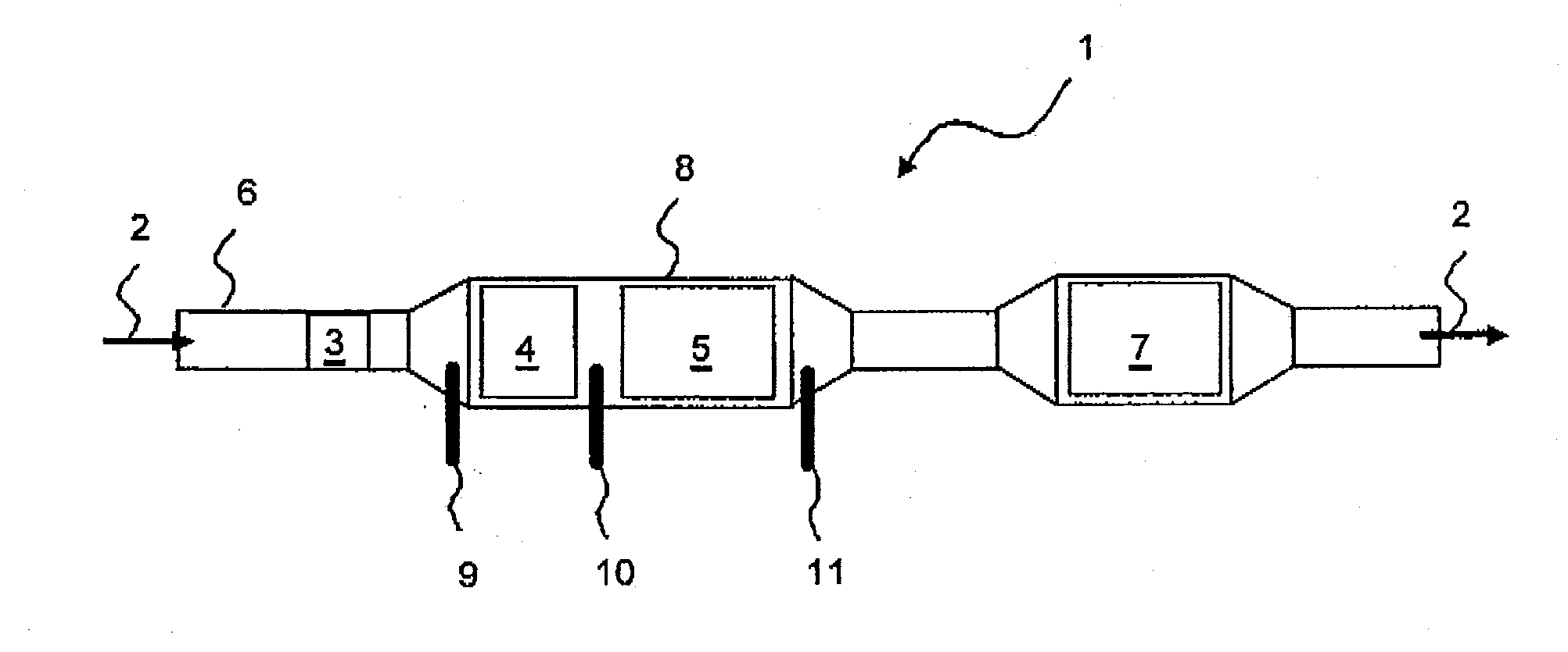
[0024]FIG. 1 is a schematic diagram of an exhaust gas system 1 to be diagnosed with regard to a flow anomaly. Arranged consecutively in the exhaust gas flow direction 2, it includes a precatalyst 3 designed as an oxidation catalyst, a main catalyst 4 designed as an oxidation catalyst, a particle filter 5, and an SCR catalyst 7. The exhaust gas system 1 is connected to an internal combustion engine (not shown) preferably in the form of a diesel motor, via an exhaust gas line 6 in a piston design. If an exhaust gas turbocharger is provided, a connection to an outlet of the exhaust gas turbocharger turbine is preferred.

[0025]The precatalyst 3 preferably comprises a coated carrier catalyst, especially a metal foil catalyst. This facilitates an at least force-fit and material connection with the exhaust gas line 6 in sections in an advantageous manner, for example in the form of a soldering or welding connection. An arrangement with a small distance to...


PUM


Abstract

In a method for the diagnostics of an internal combustion engine exhaust gas system that includes a particle filter, first and second sets of value vectors are determined, each including associated values for absolute pressure upstream and downstream of the particle filter, a differential pressure determined from the values of the absolute pressure, an exhaust gas volume flow through the particle filter, and a temperature of the exhaust gas volume flow. After a temperature-standardization of the pressure values, characteristics for dependence of the pressure values are generated from temperature-standardized values of the first set of value vectors and possibly stored as reference characteristics. By comparing temperature-standardized values for the absolute pressure on the inlet and outlet sides of the particle filter and the differential pressure of the second set of value vectors with reference characteristics, flow anomalies can be determined in the exhaust gas system.

Description

BACKGROUND AND SUMMARY OF THE INVENTION[0001]The present invention relates to a method for the diagnosis of an internal combustion engine exhaust gas system that includes a particle filter. In particular the invention provides a method for determining a flow anomaly in the exhaust gas system, based on a volume flow dependence of pressure values in the exhaust gas system.[0002]The use of particle filters to remove particles from the exhaust gas of motor vehicle internal combustion engines is common. However, such filtering leads to clogging of the particle filter over time, so that flow-through resistance increases in an undesired manner. For this reason, it is common to carry out a regeneration of the filter from time to time, so that soot particles collected in the particle filter are burnt off.[0003]The necessity of a particle filter regeneration is often determined by evaluating the value of differential pressure across the particle filter. German patent document DE 42 26 055 C1,...

Claims


Application Information

Patent Timeline
IPC IPC(8): G01N1/22
CPCF01N11/002Y02T10/47F01N2900/1406F01N2900/0402Y02T10/40
Inventor KONRAD, JOACHIMLIU, YIROUTIER, EMMANUELSISKEN, KEVINWOLF, PATRICKSCHIMMELPFENNIG, PETER
Owner VITESCO TECH GMBH
Why Eureka
Try Eureka