Method and apparatus for producing green tires

a technology of green tires and winding positions, which is applied in the direction of tires, vehicle components, domestic applications, etc., can solve the problems of deteriorating degrading the quality of green tires, and affecting the winding position accuracy, so as to improve the winding position or the winding shape accuracy, avoid the effect of inaccuracy and minimize dislocation

Inactive Publication Date: 2011-05-05
BRIDGESTONE CORP
View PDF4 Cites 4 Cited by
  • Summary
  • Abstract
  • Description
  • Claims
  • Application Information

AI Technical Summary

Benefits of technology

According to the present invention, since the rotatable winding roller is arranged close to the transfer terminal end of the liner and has a diameter larger than a distance between the winding body and the transfer terminal end of the liner, and the outer peripheral surface of the winding roller partly extends to bridge the transfer terminal end and the winding body, the unvulcanized rubber member passed from the transfer terminal end of the liner is transferred to the outer peripheral surface of the winding roller by the rotation of the winding roller and urged and press-fitted to the winding body. Thus, the unvulcanized rubber member is transferred from the transfer terminal end of the liner to the outer peripheral surface of the winding roller, while being restrained by the outer peripheral surface of the winding roller. As a result, even when vibration is applied to the transfer means due to diagonal waving, it is possible to positively avoid occurrence of inaccuracy in the winding position or the winding shape.
Moreover, since the unvulcanized rubber member is once separated from the separating member at the transfer terminal end of the liner and then transferred by the winding roller to the winding body so as to be wound around the winding body, even when the adhesion force between the liner and the unvulcanized rubber member is strong, the influence of the strong adhesion force is substantially negligible by the above-mentioned separation. Thus, the unvulcanized rubber member is prevented from stretching and floating while being wound onto the winding body. This serves to improve the quality of the green tires.
The structural features as recited in dependent claim 3 serve to readily avoid occurrence of defective adhesion of the trailing end of the unvulcanized rubber member or dislocation of the set position of the leading end, as compared to the case wherein the unvulcanized rubber member after having been cut is supplied to the winding body in the state as it is, i.e. the state wherein the leading end and the trailing end are in abutment with each other. The structural features as recited in dependent claim 4 serve to utilize the adhesion force between the liner and the unvulcanized rubber member to hold the unvulcanized rubber member during the cutting, so as to minimize dislocation of the leading end and the trailing end of the unvulcanized rubber member during the cutting, thereby effectively suppressing unexpected deformation of the unvulcanized rubber member or its re-adhesion to the liner.
The structural features as recited in dependent claim 5 serve to readily ensure that the winding body and the winding roller are driven at the same peripheral speed, immediately after starting the winding of the residual portion, thereby improving the adhesion of the residual portion. The structural features as recited in dependent claim 6 serve to save the installation cost by decreasing the number of expensive drive motors, by allowing the winding roller to undergo a following rotation.

Problems solved by technology

However, in the former type of known apparatus, since the rubber strip is passed through air between the transfer terminal end of the endless tape and the former, when vibration is applied to the transfer means from the traverser or the like, the rubber strip passing through air undergoes vibration with large amplitude.
Such vibration deteriorates the accuracy of the winding position and the winding shape of the rubber strip with respect to the former, thereby degrading the quality of the green tires.
On such occasion, the rubber strip is locally stretched to float from the former, thereby giving rise to a problem of air trap in the green tire.

Method used


Image

  • Method and apparatus for producing green tires
  • Method and apparatus for producing green tires
  • Method and apparatus for producing green tires

Examples


Embodiment Construction

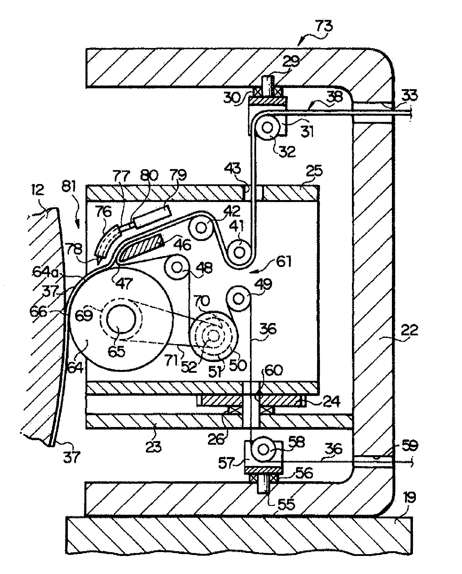
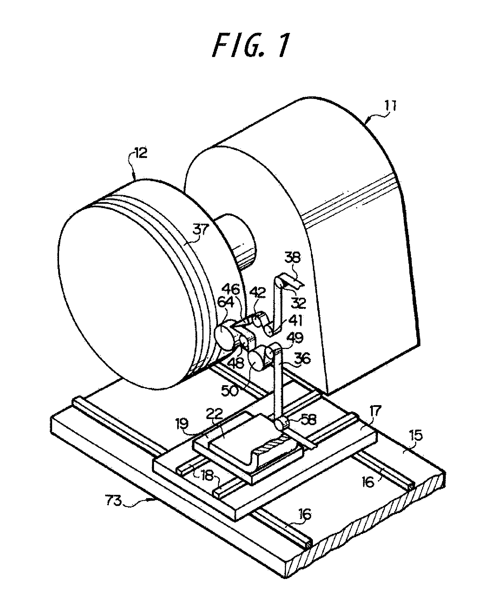
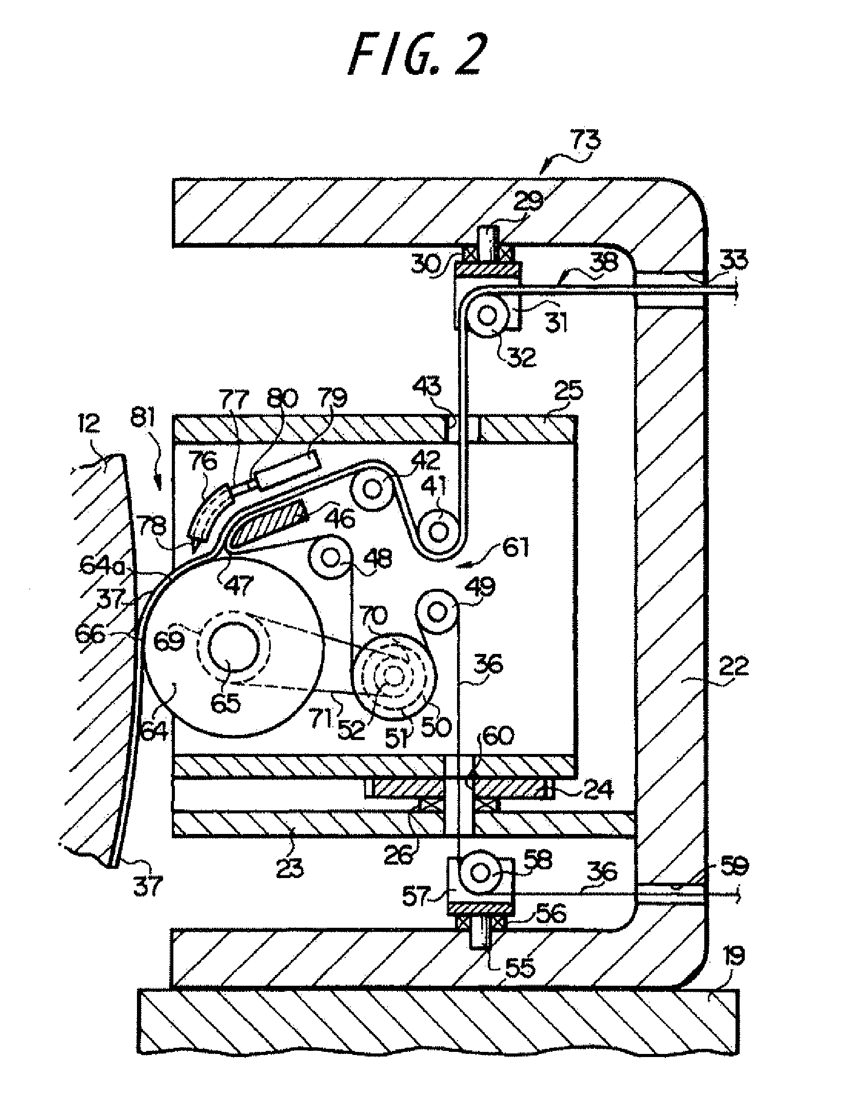
The present invention will be described below with reference to the preferred embodiment as shown in the drawings. In FIG. 1, reference numeral 11 denotes a driving section installed on a floor surface. A toroidal winding body 12 is rotatably supported by the driving section 11 so as to be rotatable about a horizontal center axis. In this instance, the winding body 12 consists of a rigid core that can be driven by the driving section 11 to rotate about the center axis which extends in the left-to-right direction, having an outer surface of the same shape as the inner surface of (product tire) and capable of being assembled or disassembled, as well as an intermediate tire body comprised of plural kinds of tire constitutive members which are adhered to the periphery of the rigid core. Incidentally, the winding body 12 may be comprised of the rigid core alone, or a cylindrical forming drum and an intermediate tire body built on the forming drum and expanded and deformed to have arcuate...


PUM

PropertyMeasurementUnit
diameteraaaaaaaaaa
flexibleaaaaaaaaaa
widthaaaaaaaaaa

Abstract

An unvulcanized rubber member passed from the transfer terminal end of a liner to the outer peripheral surface of a winding roller is transferred and press-fitted to a winding body by rotating the winding roller. By this, the unvulcanized rubber member is transferred from the transfer terminal end of the liner to the winding body while being restrained by an outer peripheral surface of the winding roller. Thus, even if vibration is applied to a transfer means due to a diagonal waving, the winding position and the wound shape of the rubber member can be maintained substantially unchanged.

Description

TECHNICAL FIELDThe present invention relates to a method and an apparatus for producing green tires by winding a ribbon-like unvulcanized rubber member multiple times around a winding body.BACKGROUND ARTConventional method and apparatus for producing green tires are disclosed, for example, in Patent Document 1 identified below.More particularly, in FIGS. 1 and 5 of Patent Document 1, there is disclosed an apparatus provided with: a transfer means including a flexible endless tape capable of running in its longitudinal direction for transferring a rubber strip toward a former rotatable about its center axis, and turned back multiple times vertically in the midcourse to form festoons, as well as a guide roller for turning back the endless tape and thereby separating the rubber strip from the endless tape at a transfer terminal end of the endless tape; a small diameter pressing roller for urging and press-fitting the rubber strip separated from the endless tape and passed through air a...

Claims


Application Information

Patent Timeline
Patent Type & Authority Applications(United States)
IPC IPC(8): B29D30/08
CPCB29D30/3028B29D30/28
Inventor OGAWA, YUICHIRO
Owner BRIDGESTONE CORP
Why Eureka
Try Eureka