Mounting Device for Internal Circlip

a technology of mounting device and internal circlip, which is applied in the direction of machine supports, manufacturing tools, other domestic articles, etc., can solve the problems of reducing labor intensity and inability to pre-compress workpieces, and achieve excellent guiding effect and flexibility.

Inactive Publication Date: 2011-05-05
XU XIAOHUA
View PDF4 Cites 14 Cited by
  • Summary
  • Abstract
  • Description
  • Claims
  • Application Information

AI Technical Summary

Benefits of technology

[0005]It is an object of the present invention is to provide a mounting device for internal circlip with excellent guiding effect and flexibility to avoid above problems such as no auxiliary guide / pre-compression and deviation.
[0012]A circlip storage is provided on the top surface of the sleeve fixation board beside the sleeve, the circlip storage has a guide board matching a opening of the circlip, a feeding board having a smaller thickness than the circlip axial is movable between the guide board and the sleeve fixation board, the sleeve has an entrance allowing the feeding board to insert. A number of circlips can be pre-stored in the circlip storage so as to increase efficiency. The feeding board can position the circlips to make them orderly pile in the circlip storage.
[0013]The middle of said circlip core rod is provided with an annular step surface, which can contact with the top surface of the sleeve. The annular step surface can contact to the top surface of the sleeve so as to limit the down stroke of the circlip core rod and to prevent the circlip core rod from over effect with the inner cone hole of the sleeve. So it protects the device (prolong its service life) and the parts of the work piece.
[0016]The inner cone hole of the sleeve has a cylindrical section at the big top opening and a cylindrical section at the small bottom opening The cylindrical section at the big top opening make it easy for the circlip to enter in the inner cone hole of the sleeve and the cylindrical section at the small bottom opening make it easy to form a transition between the inner cone hole and the work piece and easy for the circlip to enter the groove.
[0017]The bottom of said circlip core rod forms a cavity and the top of the circlip core rod is connected with the piston rod of the cylinder by screw connection. The cavity is to ensure the axis of work piece is placed in the cavity when mounting the circlip to prevent the axis of work piece from obstructing the descending of the circlip core rod. It also prevents the circlip core rod from damaging the axis of work piece.
[0019]Therefore, this invention has an excellent guiding effect to ensure the circlip can be easily mounted.

Problems solved by technology

Above work piece to some extent reduces the labor intensity but there are some problems during mounting: 1. Upper die head is only driven by the cylinder without any auxiliary guide.
Pre-compression of the work piece is impossible.

Method used


Image

  • Mounting Device for Internal Circlip
  • Mounting Device for Internal Circlip
  • Mounting Device for Internal Circlip

Examples


Embodiment Construction

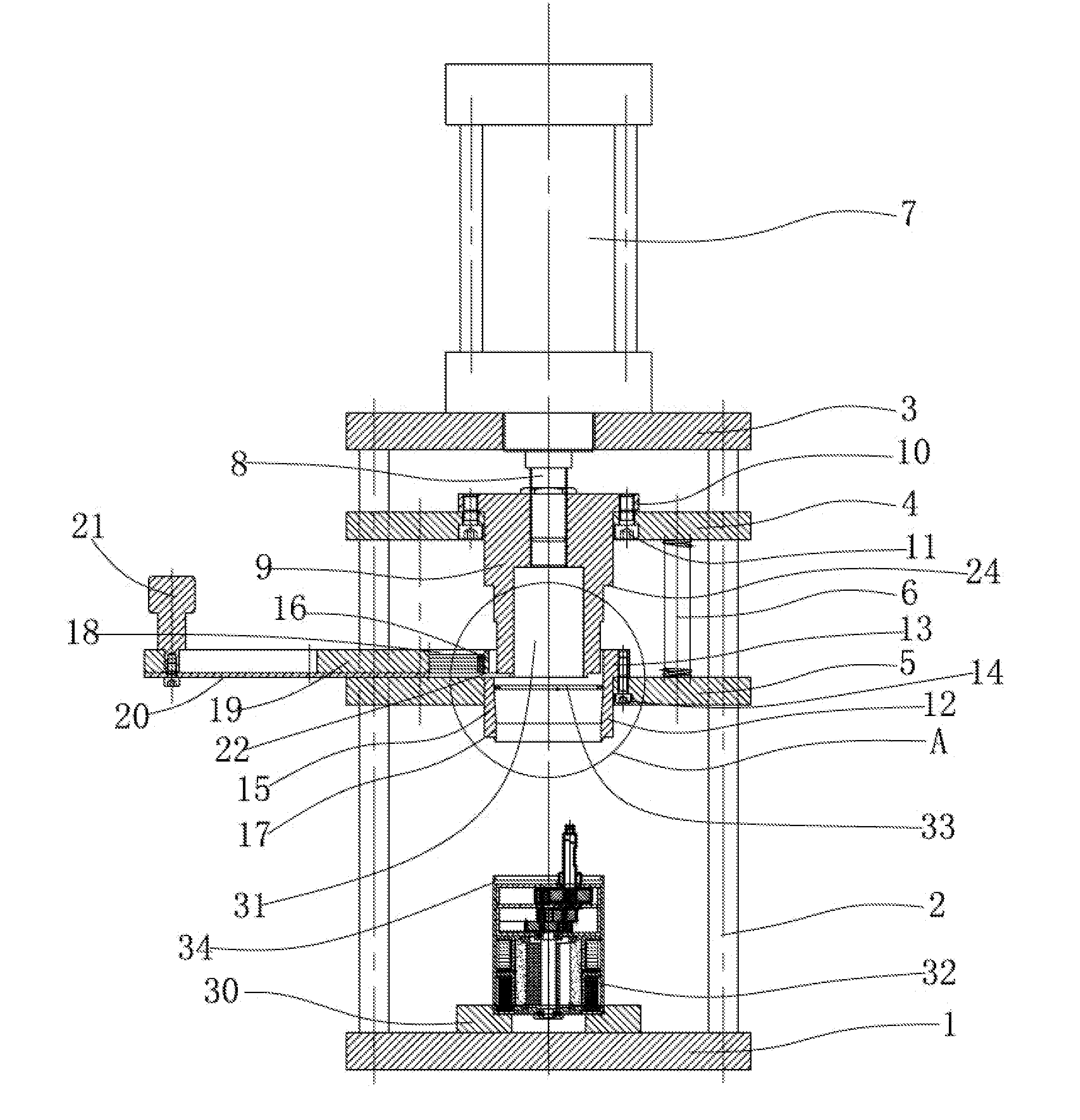
[0023]As shown in FIG. 1, a mounting device for internal circlip includes a device frame composed of a base board 1, a cylinder fixation board 3 and two perpendicular sliding guides 2 located between the base board 1 and the cylinder fixation board 3 and fixed thereof A core rod fixation board 4 and a sleeve fixation board 5 are movable on the two sliding guides 2. The core rod fixation board 4 is above the sleeve fixation board 5. Two compression springs 6 are located between the core rod fixation board 4 and the sleeve fixation board 5.

[0024]A cylinder 7 is fixed on the cylinder fixation board 3. A piston rod 8 of the cylinder 7 passes through the cylinder fixation board 3 and then fix a top of a circlip core rod 9 through thread. The core rod fixation board 4 has a core rod mounting hole, the circlip core rod 9 forms a shoulder 10, the circlip core rod 9 is put in the core rod mounting hole, then is fixed with the core rod fixation board 4 together by bolts 11. A bottom of the ci...


PUM


Abstract

A mounting device for internal circlip comprises a device frame composed of a base board, a cylinder fixation board and at least two perpendicular sliding guides located between the base board and the cylinder fixation board and fixed thereof; a core rod fixation board and a sleeve fixation board being movable on the at least two sliding guides, the core rod fixation board being above the sleeve fixation board, at least two compression springs being located thereof; a cylinder fixed on the cylinder fixation board, a piston rod of the cylinder passing through the cylinder fixation board being fixed on top of a circlip core rod, the circlip core rod and the core rod fixation board being fixed together and a bottom of the circlip core rod extending to a top of the sleeve fixation board; a sleeve coaxial with the circlip core rod being fixed on the top of the sleeve fixation board, the sleeve having a inner cone hole with a big top opening and a small bottom opening, a bottom of the circlip core rod can pass through the small bottom opening of the inner cone hole, and an orientation board for a work piece being fixed on the base board at where is under and aimed at the sleeve. The device of the invention has good guide performance, and it could ensure success mounting of the circlip and could be operated conveniently.

Description

FIELD OF THE INVENTION[0001]This invention is a mounting device for internal circlip. It belongs to circlip mounting device area.DESCRIPTION OF THE PRIOR ART[0002]In some of the motor assembly structures, there is a method to use internal circlip inside the motor to fix the position of the end cover, that is, to form a groove inside the motor and mount the circlip afterwards. Firstly put the contracted circlip in the motor and when the circlip reaches to the groove it will stretch out with its own elastic force.[0003]Someone proposes a press mounting device of internal circlip (publication number: CN2834799Y) including the base. On top of the base it is the upper die head driven by a cylinder and at the bottom of the base (opposite the upper die head) it is the work piece positioning base. There is a guiding sleeve in the device with a matching cavity shaped like a wedge.[0004]Above work piece to some extent reduces the labor intensity but there are some problems during mounting: 1....

Claims


Application Information

Patent Timeline
Patent Type & Authority Applications(United States)
IPC IPC(8): F16M13/00
CPCB25B27/20B23P19/084
Inventor HU, HONGYUANWU, XIAOFENG
Owner XU XIAOHUA
Why Eureka
Try Eureka