Airborne/spaceborne oil spill determining system

a technology of airborne space, which is applied in the field of airborne/spaceborne oil spill determining system to achieve the effect of high radiometric sensitivity

Inactive Publication Date: 2011-05-05
ALAWADI FAHAD A M I
View PDF8 Cites 11 Cited by
  • Summary
  • Abstract
  • Description
  • Claims
  • Application Information

AI Technical Summary

Benefits of technology

This patent describes a device that can detect oily substances on water surfaces by taking pictures of them with a special camera. It uses different colors to measure how much light is absorbed by the oil. By analyzing these measurements, it can create a map showing which parts of the water are most likely to have oil spills. This helps people who work at cleaning up the ocean quickly find the places where they should start looking first.

Problems solved by technology

The technical problem addressed in this patent is the need for an airborne system that can detect oil spills and other contaminants on a water surface using standard resolution information from a moderate resolution imaging spectroradiometer/MODIS or similar optical scanner facility. The system can also identify areas where significant concentrations of oil or related contaminants are encountered and alert for immediate attention.

Method used


Image

  • Airborne/spaceborne oil spill determining system
  • Airborne/spaceborne oil spill determining system
  • Airborne/spaceborne oil spill determining system

Examples


Embodiment Construction

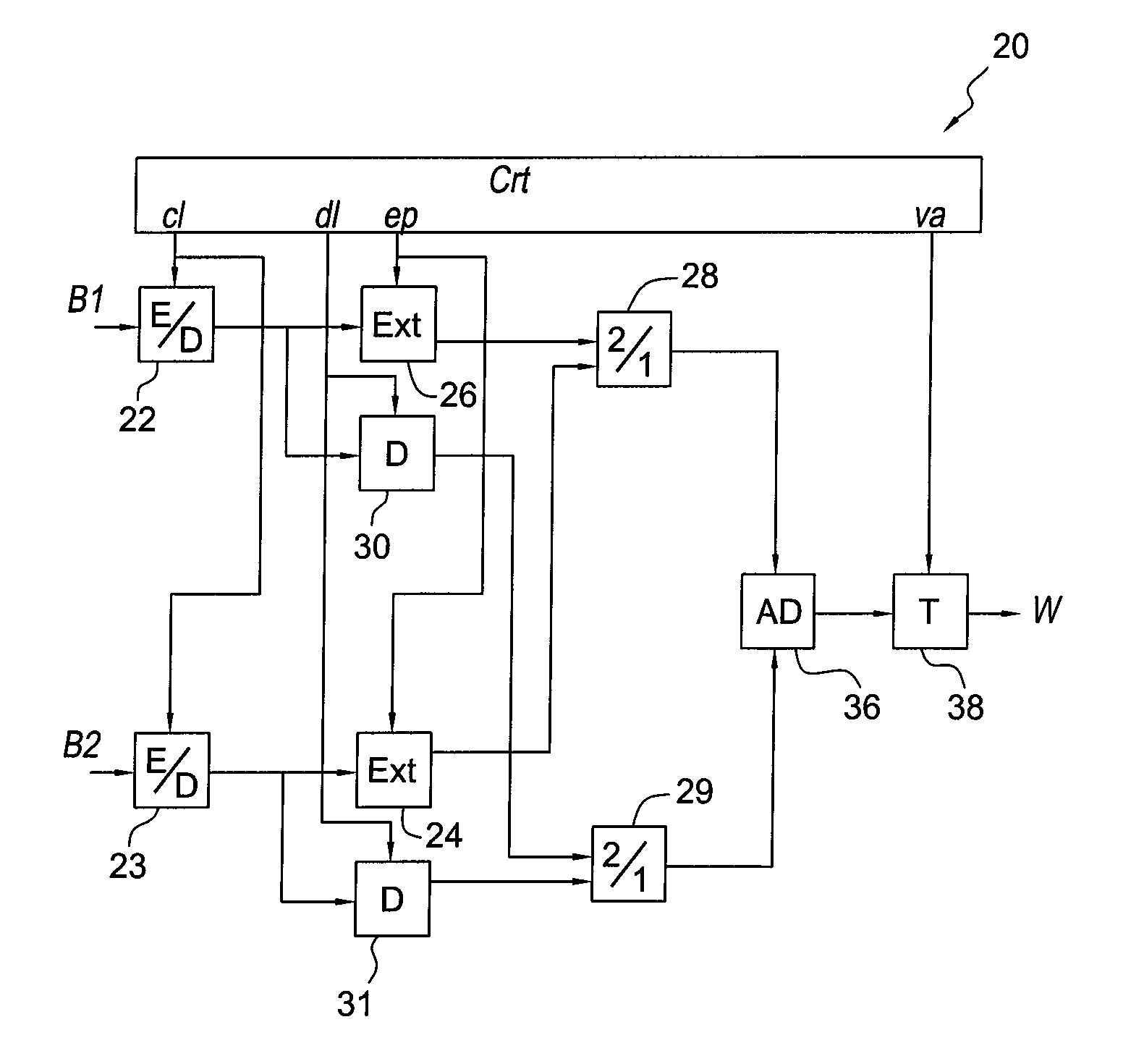
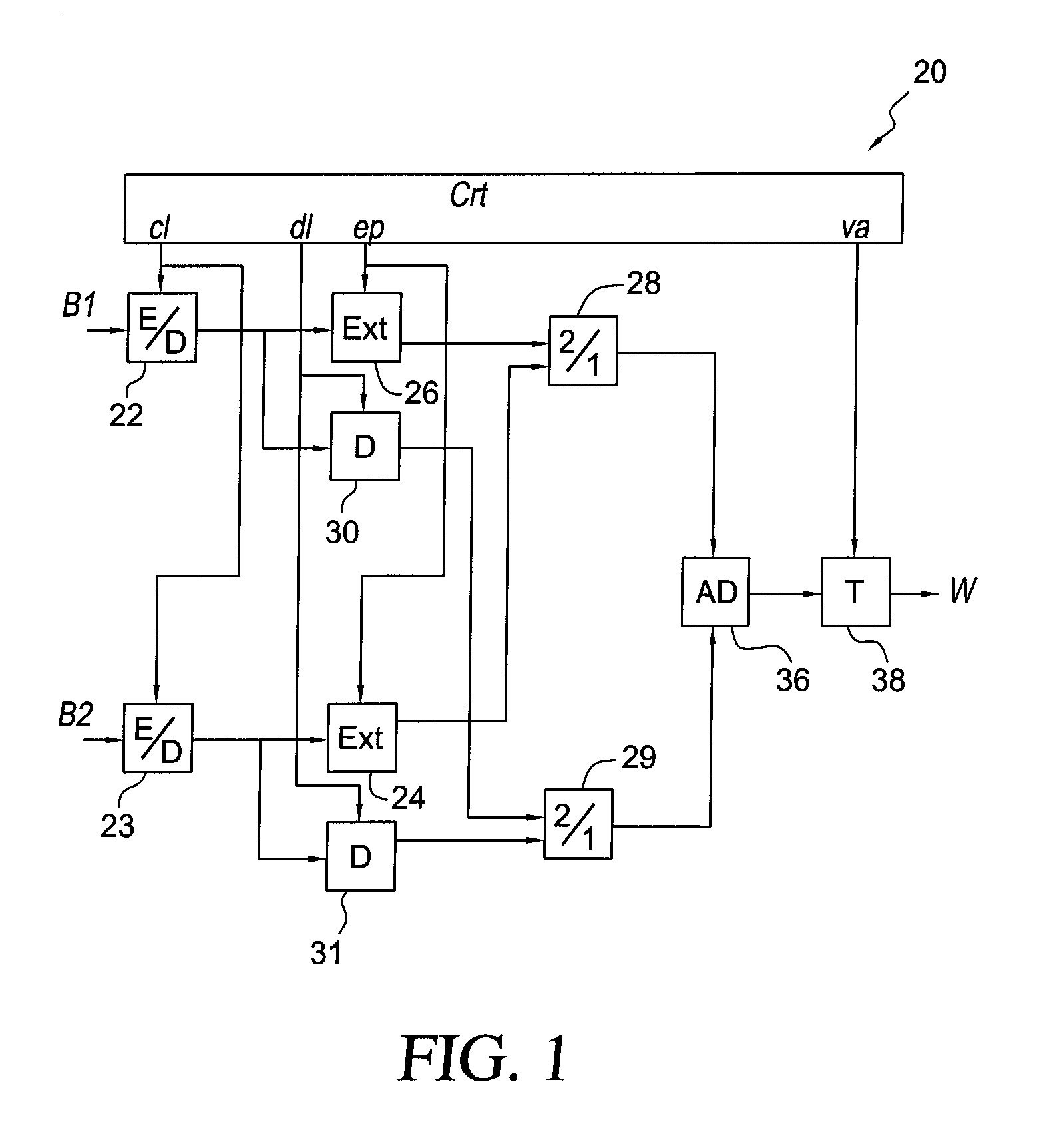
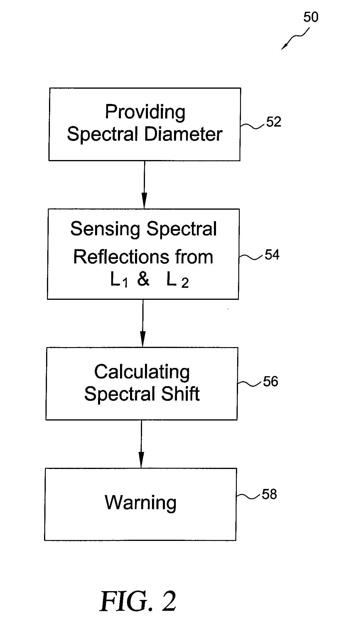
[0017]A method for oil pollution and other contaminants on water surfaces in accordance with the present invention is based on calculating the spectral passive reflection response from two optical bands. One of the bands is in the near inferred (NIR) band while the other band is outside of the NIR band i.e. in the visual band. One of the bands is taken from the surface of water that is suspected of having pollution while the other is from an adjacent area that is believed to be clear water. The 250 m resolution bands one and two belonging to the Moderate Resolution Imaging Spectroradiometer (MODIS) can be implemented in the device or by means of a similar passive optical scanner and from various platforms. According to a constant value labeled “Spectral Contrast Shift” (SCS) calculated on-site and in real-time from both bands, a warning is issued in response to an oil spill or other contaminant on the water surface.

[0018]The SCS method was derived by using the spectral ratios betwee...


PUM


Abstract

An airborne/spaceborne oil spill detection method includes the step of providing a moderate-resolution-imaging-spectroradiometer and sensing the spectral reflections from two optical bands one of which is in the near inferred range. The spectral contrast shift from two adjacent areas of water are calculated and a warning issued when an oil spill or other contaminant is detected. A system for detecting an oil spill or other contaminant on the surface of water is also disclosed.

Description


Claims


Application Information

Patent Timeline
Owner ALAWADI FAHAD A M I
Why Eureka
Try Eureka