
Deployable power supply system

a power supply system and self-contained technology, applied in emergency power supply arrangements, cell components, cell component details, etc., can solve the problems of affecting the delivery of power, affecting the efficiency of power supply, and affecting the availability of power, so as to facilitate the diffusion and adoption of renewable energy, facilitate the operation, scale, maintain and transport, and facilitate assembly, service and transportation.

Inactive Publication Date: 2011-05-05
ZEROBASE ENERGY
View PDF54 Cites 5 Cited by
  • Summary
  • Abstract
  • Description
  • Claims
  • Application Information

AI Technical Summary

Benefits of technology

[0007]These and other objectives are achieved with the present invention, which is a deployable power supply system including a standardized housing and a modular arrangement for supplying energy using an array of renewable and non-renewable energy sources. The system of the present invention obviates the problems associated with customized complexity with a simple-to-install arrangement that is easy to operate, scale, maintain and transport, and which catalyzes the diffusion and adoption of renewable energy. More particularly, the present invention provides a dedicated platform designed to receive and integrate elements in an efficient, easily assembled, serviced and transported manor. The combined elements establish an energy conversion system that takes and / or makes energy, stores that energy, and enables the transfer of that energy. The easy usability and transportability of the system facilitates the rapid and broad deployment of clean energy to regions and situations where clean, fuel-free energy is an advantage, but is unavailable due to the non-existence of deployable renewable energy sources. The invention offers relief groups, the military, first-responders, homeowners and others a fast, clean-energy option wherever they are located.
[0008]The invention hybridizes renewable power generation and uses an open architecture approach, incorporating any common, off-the-shelf or custom-constructed or configured power production, power storage, and / or power management components. The interchangeability of power production devices lends flexibility to application and output. A standardized, plug-and-play interconnection design lets any technology easily connect to the system's central interface structure. The system is manageable via remote diagnostics and control. It is scaleable, with each stand-alone unit rapidly linkable to the next in a “daisy chain” of power. Because the system is preferably arranged to generate its primary power from renewable energy, heat, noise and emissions signatures are significantly reduced. The system is an important alternative for customers in a wide range of markets including healthcare, security, any of a variety of government functions, and tourism.
[0011]The invention is a system or, more specifically, an apparatus, incorporating a network of devices for producing and delivering power at a desired location via integrating power generation, storage, management and system reporting devices that, in aggregate, includes a first device or set of devices for generating electrical power from ambient (renewable) resources which is / are contained within or coupled to the apparatus, an optional second device or set of devices for generating electrical power from ambient resources or fossil resources which are / is contained within or coupled to the apparatus, a third device or set of devices for conducting the electric power from the first device and optional second device through the apparatus, a fourth device or set of devices for modulating the electrical power and converting it as needed, a fifth device or array of devices for storing power which is / are contained within or coupled to the apparatus, an optional sixth device or set of devices for information reporting of the performance of the system, all of which devices are containable in a conveyable housing, preferably of composite material construction (but not limited thereto), wherein the housing is of a design that is resistant to the elements and which allows for facile and rapid maintenance of the system. The system preferably is of modular form to allow for relatively easy integration, access to and removal of the devices.
[0015]The housing is of a modularized configuration and preferably includes one or more drawers, doors and access points for the purpose of easy and rapid servicing and maintenance of the system. For example, power generating equipment may be easily inserted into and removed from the housing. For purposes of the description of this invention, a “drawer” may be any type of device suitable for retaining thereon or therein one or more components, whether fixed or removable components. The drawer or drawers may be fixed, removable, slidable, rollable, or in some other manner movable from within the housing partially or completely out of the housing and back again. The housing incorporates materials and configurations to be as impervious as reasonably possible to the elements, including all-weather seals, marine venting, and such other features as those skilled in the art of outside housing structures would employ. The housing is preferably arranged for tamper resistance such as including, for example, anti-theft attachment devices to restrict access to the interior of the system to authorized personnel only. The system may be made in varying sizes and dimensions for varied applications. The housing is arranged to receive power from at least one of the first and second power generating devices within the conveyable housing, and to provide access to the received power in a plurality of different electrical configurations such as, for example, standard electric power conducting cords and / or sockets. The housing may also be arranged to provide for a plurality of coupling elements to be secured to the housing and configured to allow for the attaching of more than one type of power generating and storage device to the housing.

Problems solved by technology

Traditional portable generators exist for such instances; however, they are bound to fossil-fuel energy sources that may not be available in sufficient supply for extended periods of time.
Traditional back-up power products, based on fossil fuels, are problematic.
Issues of fuel delivery, maintenance, noise, and emissions restrict their feasibility and hamper the delivery of power to those who need it.
Traditional renewable energy installations are complex projects involving the purchase and integration of multiple components in customized configurations.
Solar energy projects, for one, require long lead times, professional analysis of installation sites, and the purchase of difficult-to-integrate power generation and management systems that, once installed, are permanent and difficult to expand.
Attempts have been made to design portable power supplies including renewable energy sources; however, they are of limited desired commercial interest for a variety of deficiencies.
One limitation is that they are custom structures of unique design for specific applications.
Another limitation is that they are not readily integrated into existing power transfer systems.
Yet another limitation is the portable container used to contain the power source components.
They may not be appropriately formed or fabricated to make them convenient for use or movement, they may not be suitable for protecting the internal components in the environments to be experienced, or a combination of both limitations.

Method used


Image

  • Deployable power supply system
  • Deployable power supply system
  • Deployable power supply system

Examples


Embodiment Construction

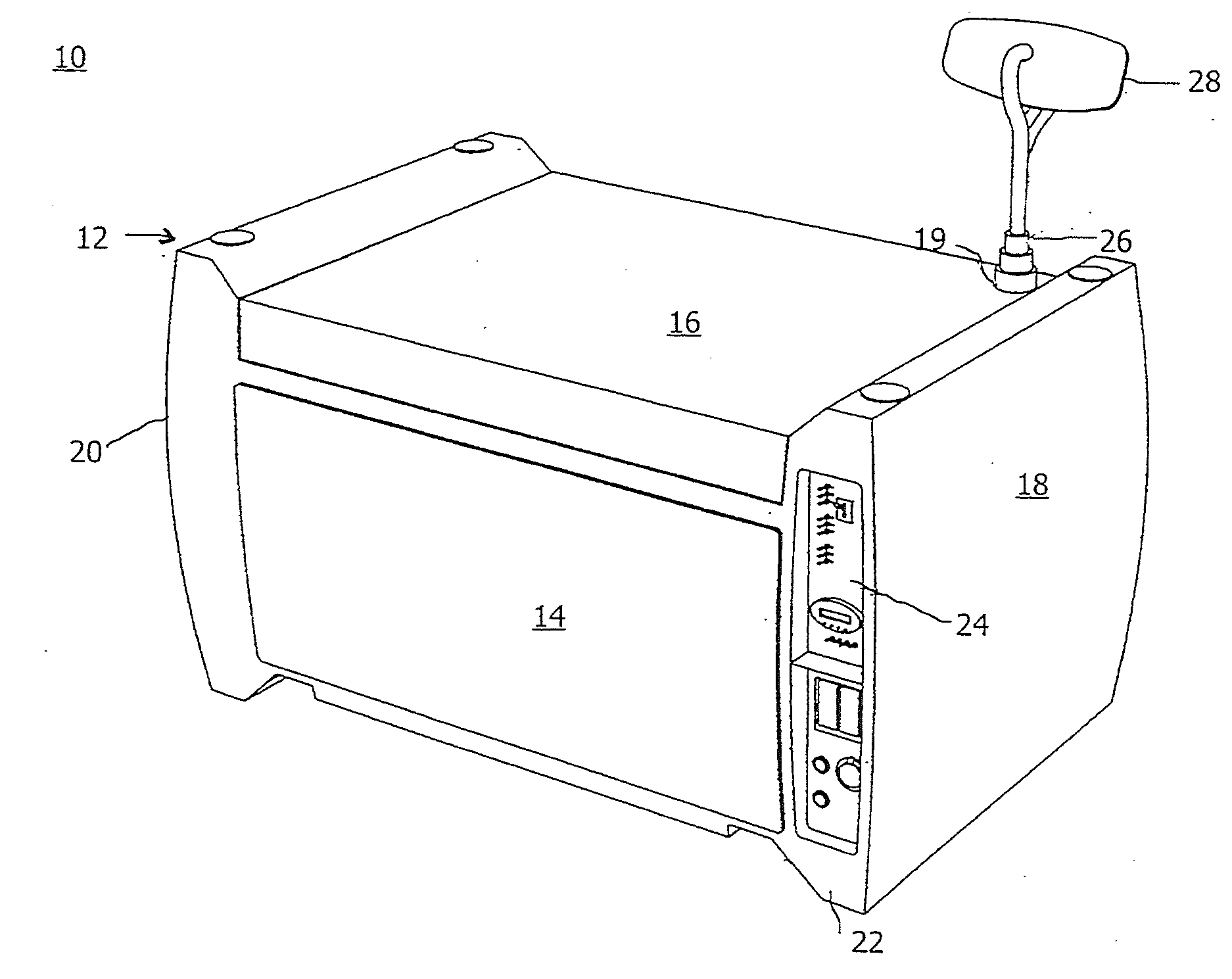
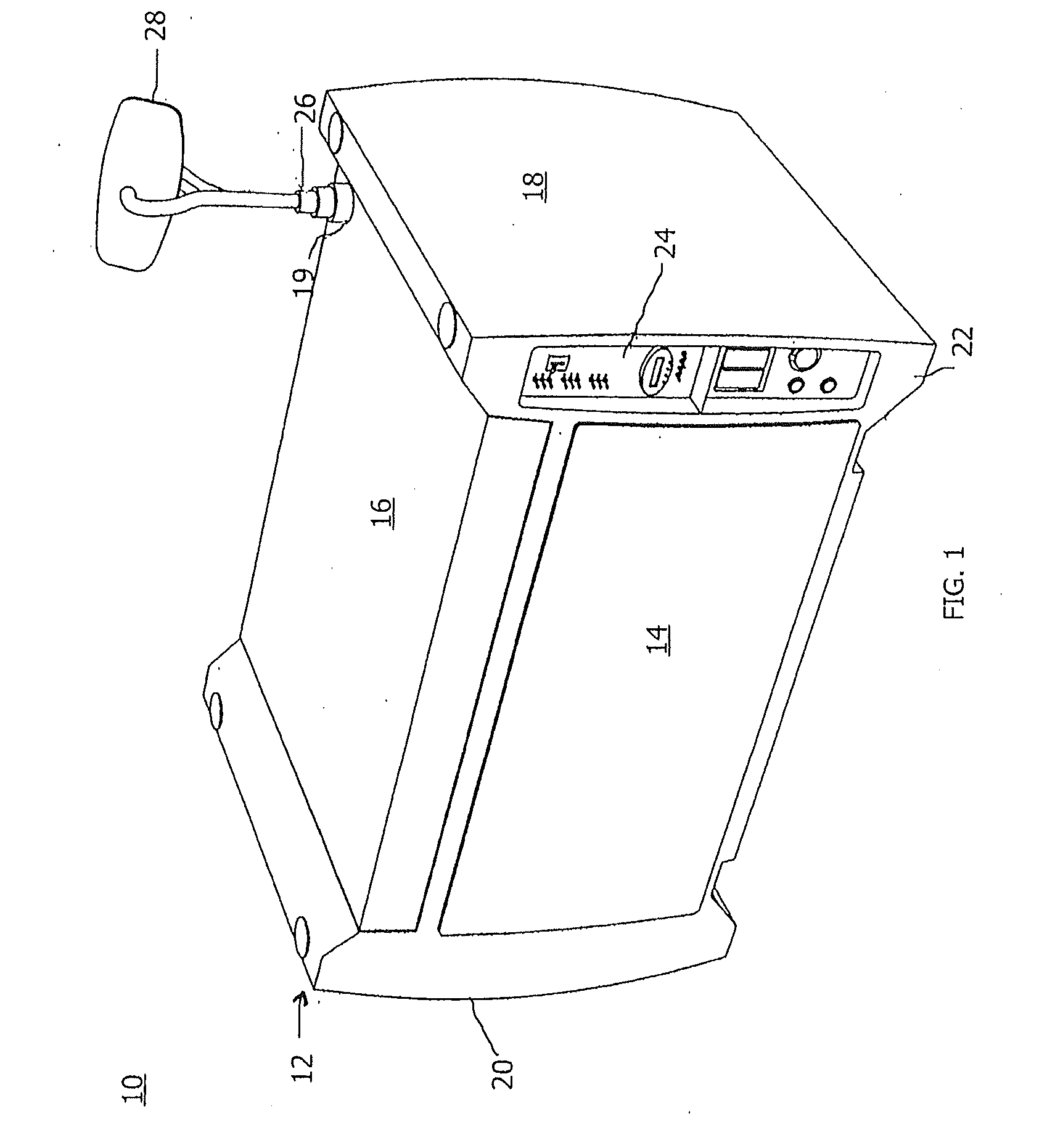
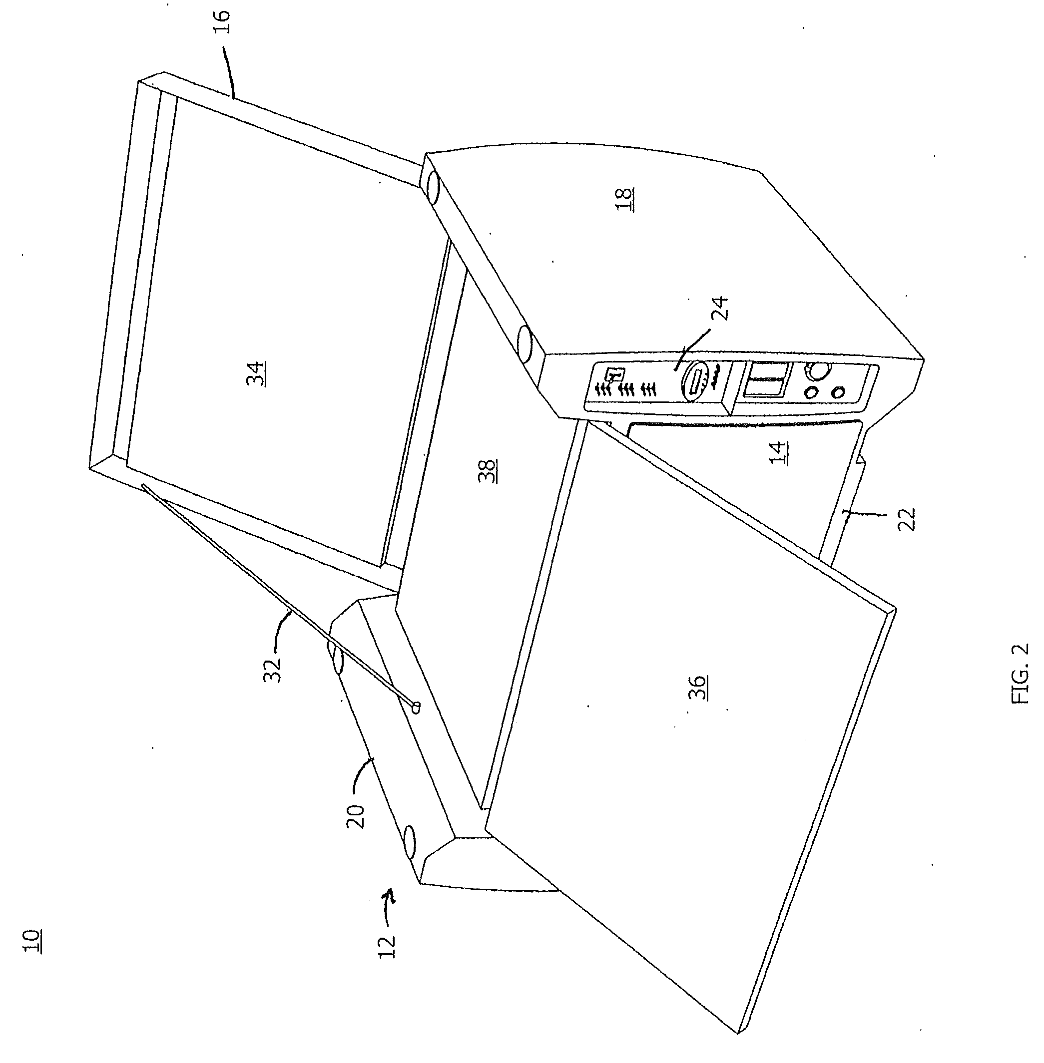
[0034]The present invention shown in FIG. 1 is a deployable power supply system 10 embodied in a housing 12 arranged for relative ease of movement and for storage of a plurality of components associated with power supply functionality at any selectable location, The housing 12 includes a front panel 14, a top panel 16, a first side section 18, and a second side section 20. The front panel 14 is removably attachable to a primary casing 22 and may be affixed to the primary casing 22 with attachment means, such as anti-theft components, such as security bolting, for example. Anti-theft attachment components restrict access to devices within the housing 12 to authorized personnel only. The top panel 16 is hingedly or removably connected to the primary casing 22 to enable rotatable opening thereof. The first side section 18 includes a control panel 24 for management of power generation and distribution, and any other control functions of interest for the system 10. The first side section...


PUM


Abstract

A deployable power supply system is provided. A primary casing and a moveable panel includes a first side section, a second side section, a front side, and a rear side, the moveable panel having a top panel forming a top portion of said housing. The first side section of at least one of the primary casing and the moveable panel includes a first upper portion and the second side section of at least one of the primary casing and the moveable panel includes a second upper portion. The first upper portion and the second upper portion extend beyond the top portion of the housing to form a cavity therebetween, the top panel being disposed within said cavity.

Description

CROSS REFERENCE TO RELATED APPLICATIONS [0001]The application is a continuation of U.S. application, Ser. No. 11 / 836,335, filed Aug. 9, 2007, the contents of which are incorporated herein by reference thereto.BACKGROUND OF THE INVENTION [0002]The present invention relates to self-contained power supply systems. More particularly, the present invention relates to systems that may be deployed to remote locations and that provide a self-contained power supply. Still more particularly, the present invention is a self-contained, conveyable energy conversion and storage device using ambient resources as the primary energy source. The system may include a plurality of power sources, including ambient power sources.[0003]There are many instances in which portable power supplies are required, or at least preferred. In one instance, power may be required at a location where the primary power grid is not functioning, particularly where critical resources must be maintained. In another instance...

Claims


Application Information

Patent Timeline
Patent Type & Authority Applications(United States)
IPC IPC(8): H02J9/00H01M50/209H01M50/222H01M50/271H01M50/296H02S30/20
CPCH01M2/1022H01M10/46H01M2250/30H02S10/10Y02B10/14Y02B90/18H02S30/20H02J7/355H02S10/40H02J7/35Y02E10/50Y02B10/10Y02B90/10Y02E60/50Y02E60/10H01M50/209H01M50/222H01M50/296H01M50/271
Inventor LYMAN, ZACHARYLYMAN, CABOTGENTENAAR, HENRY
Owner ZEROBASE ENERGY
Learn More