Data-transmission system

a data transmission system and data technology, applied in the field of data transmission systems, can solve the problems of difficult logistical applications, poor applicability of the above solutions, and high power consumption, and achieve the effects of improving system usability, saving power, and usability

Active Publication Date: 2021-06-17
LOGMORE OY
View PDF7 Cites 0 Cited by
  • Summary
  • Abstract
  • Description
  • Claims
  • Application Information

AI Technical Summary

Benefits of technology

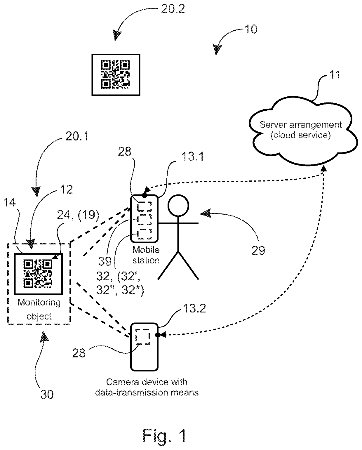
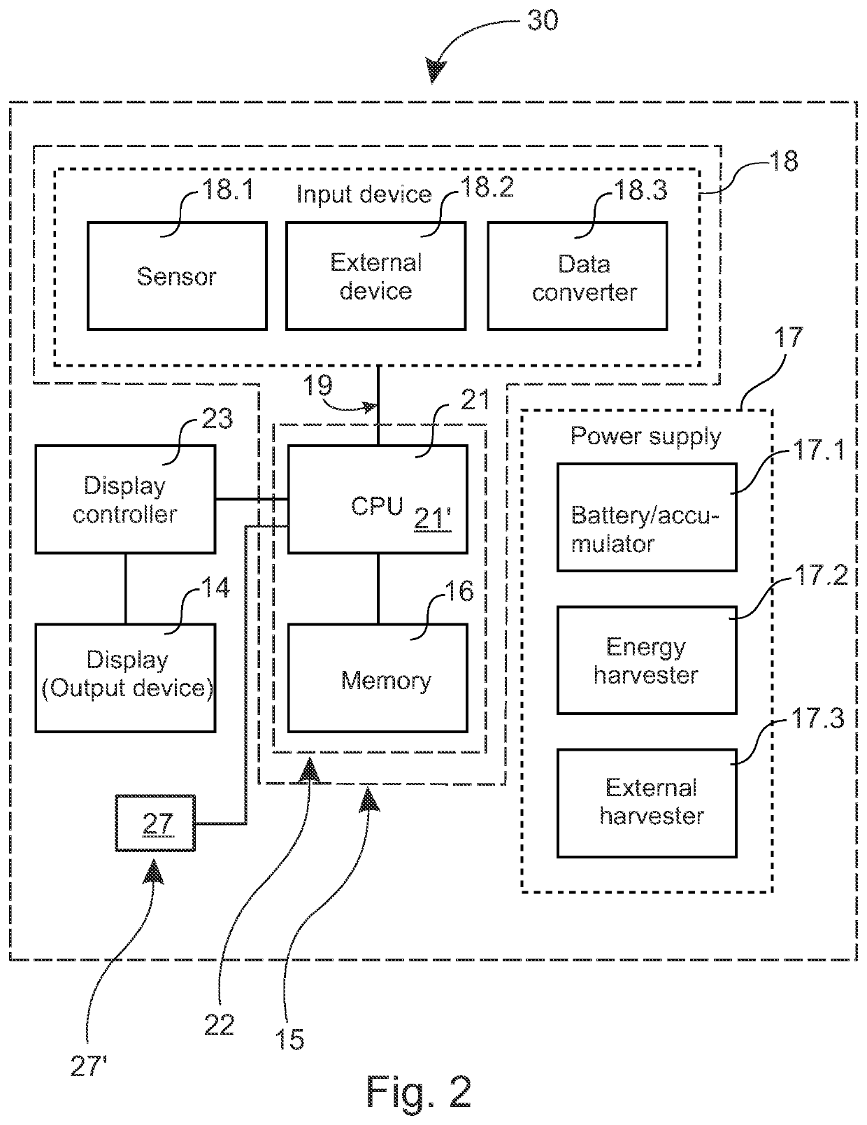
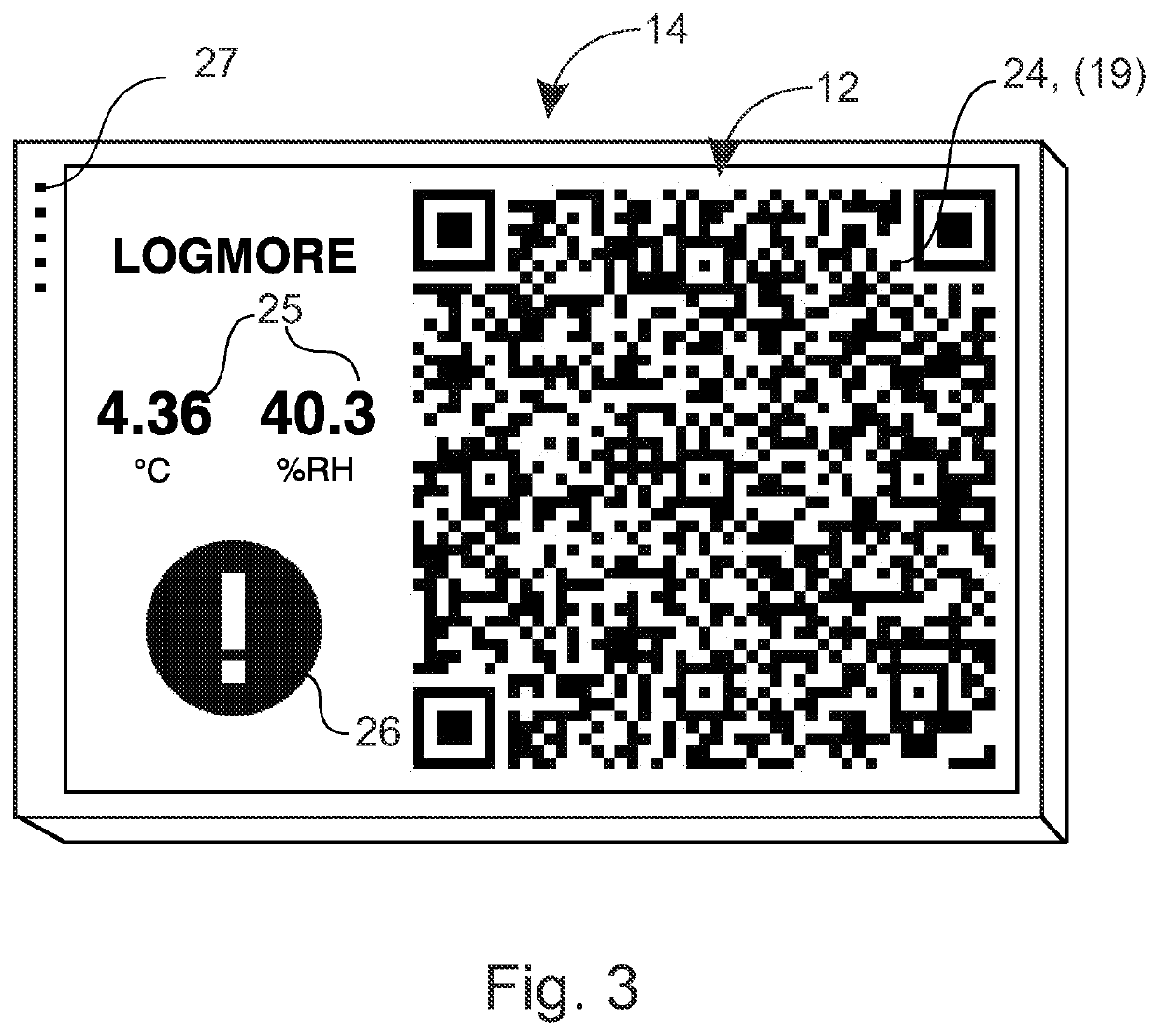
[0010]A significant advantages relating to the usability of the system is also achieved with a property of the output device, according to which it is to be arranged to show code readable on the reader device at a zero-power in a passive state. In addition to saving power, the measurement means can be implemented as self-powered, the code can be read if wished, nor does its presentation necessarily demand special actions by the user. This is a significant usability advantage in large-volume applications, in which there can be many monitoring objects to be read, and actions relating to bringing the code up slow down operation. Owing to the property, code can be read, for example, continuously.
[0011]According to one embodiment, in the invention two-way data transmission can also be used between the measurement apparatus formed of the measurement means and the output device, and the server arrangement, preferably transmitted by the reader device. Thus, in addition to the measurement data being transmitted from the measurement means to the server arrangement, the measurement apparatus can also be controlled using the server arrangement, or even more particularly through the server arrangement. The reader device can perform several different tasks in this control. The reader device can be used to set the settings of the measurement apparatus. This can include, for example, using the reader device to enter settings in the measurement apparatus. The settings can, in turn, come from the server arrangement or initially from the reader device itself. Thus making measurement-apparatus settings using the reader device can, in addition to entering settings, include also making settings, which thus takes place by the reader device to the server arrangement, before the programming of the measurement apparatus respectively. On the basis of making of settings by the reader device, or of settings made to the server arrangement in some other way, the server arrangement can form, for example, web content, in which the settings are coded and which is then received from the server arrangement using the reader device. The reader device then for its part enters the settings, coded in this web content, in the measurement apparatus. This then also improves the system's usability, because settings relating to the measurement apparatus can easily be made, even using as such known consumer devices, without demanding of them additional properties, functions, or software.
[0012]In addition, according to one embodiment, owing to two-way data transmission the reader device can read measurement data from the measurement object, which does not fit with one visual code. The reader device can preferably request the next code immediately it has read the previous code and sent it to the server arrangement. This also permits large amounts of data to be easily read. In addition, two-way data transmission can also permit the excitation of the measurement apparatus and / or the output device belonging to it and also the synchronization of the measurement apparatus's clock by the server arrangement.
[0013]According to one embodiment, the invention also allows low power to be used to implement encryption. One possible way to implement low-power encryption is one-use key encryption based on a random number and the XOR encryption method. This offers a simple way to implement energy-efficient encryption that also demands a relatively small amount of memory, without encryption algorithms that need greater processor power.
[0014]Owing to the invention, it is possible to implement an improved, user-friendly, energy-efficient, and data-secure data-transmission system for collecting, creating, transmitting, and processing object data. A low-power output device, a processor and memory belonging to the measurement means, the capacity of which is also arranged to suffice for the service life of the measurement apparatus and / or monitoring object, combined with easy usability and efficient but simple possible encryption permits the said advantages of the data-transmission system according to the invention and the improvements relative to known systems. Other characteristic features and advantages of the invention may be appreciated from the following detailed description considered in conjunction with the accompanying drawings.

Problems solved by technology

Some drawbacks in the aforementioned solutions are, however, their high power consumption and then poor applicability to objects lacking a continuous external power supply.
In addition, the applicability of the above solutions, for example, to logistical applications is challenging.
This creates a challenge for the usability of the system.
In addition to the above, controlling the operation of the measurement means also relates to the same user-friendliness problem, such as their programming, for example, during start up.
The measurement means therefore cannot be equipped with demanding data-inputting means, because their price would then rise and thus their usability particularly in large-volume applications would weaken.
The amount of data to be transmitted with QR code is also limited and often insufficient.

Method used


Image

  • Data-transmission system
  • Data-transmission system
  • Data-transmission system

Examples


first embodiment

[0088]Machine-readable code with a low power consumption, which is particularly suitable, for example, for mass products with a relatively short delivery cycle in the logistics chain, can also be created as follows. shown in FIG. 9a, a character display 12′ can be used. It is arranged to show main part, for example, of QR code 24 using, for example, one bit. Embedded in the QR code 24 is, in addition, an area 12″ of at least one data-pixel, which is arranged to show data to be transmitted (for example, has temperature remained / not remained within set limits). Instead of QR code 24, for example, some 2d code according to standard, such as aztec code or similar, can equally be used to the creation of a static area 12′ and the area 12″ containing changing data.

second embodiment

[0089] which is shown in FIG. 9b, most of the QR code 24 shown on the output device 14 is a preprinted pattern 12′″. In addition, there is in the QR code 24, now in its centre, a data area 12″ for data transfer, formed of at least one data-pixel. The preprinted pattern 12′″ can show, for example, most of or entirely the server's address, or other similar unchanging information. The preprinted pattern 12′″ can be read and defined, for example, at the first reading. At the first reading, in addition to the server address or separately, at the second separate reading, read the data-pixels of the QR code 24, which is now in the middle of the data area 12″, in which is at least one pixel. Here or also in the previously presented embodiment, the changing data area 12″ can be implemented, for example, using an LCD display or similar.

[0090]FIG. 11 shows one way to implement the changing data area's 12″ otherwise statically implemented QR code 24. The data area 12″ is now formed using a smal...


PUM


Abstract

A data-transmission system, comprising measurement means, having memories, to create and collect measurement data, an output device having a zero-power passive state, to show in the zero-power passive state, machine-readable code containing the measurement data created using the measurement means, a power supply for the output device and the measurement means, a server arrangement to process and/or store the measurement data, and one or several reader devices to read the code from the output device in the zero-power passive state and arranged for data transfer with the server arrangement. The output device and measurement means with memories are to be arranged at monitoring objects.

Description

CROSS-REFERENCE TO RELATED APPLICATIONS[0001]This application is a U.S. National Stage of International Patent Application No: PCT / FI2018 / 050805 filed on Nov. 5, 2018, which claims benefit of Finland Patent Application No. FI 20175981 filed on Nov. 3, 2017.TECHNICAL FIELD[0002]The invention concerns a data-transmission system.BACKGROUND OF THE INVENTION[0003]A monitoring solution exploiting dynamic QR code, more generally code, is known from international patent application publication WO 2013 / 046231 A1. In it, when the state of the object being monitored changes, the QR code is also updated to correspond to the state. In other words, the state data of the object can be included in the QR code contained the server's URL address. The QR code can be read, for example, using the camera of a mobile device and a QR code application in an as such known manner. On the basis of the reading, a service request is sent to the server individuated by the QR code and, using the same service reque...

Claims


Application Information

Patent Timeline
Patent Type & Authority Applications(United States)
IPC IPC(8): G06K19/06G06K7/10
CPCG06K19/06112G01D9/005G06K7/1095G06K19/06131H04Q9/00H04Q9/04G01D9/00
Inventor JUHALA, JANNETAPIO, ANTTI
Owner LOGMORE OY
Why Eureka
Try Eureka